Color reproduction system

a color reproduction and color technology, applied in the field of color reproduction systems, can solve problems such as the problem of accurately reproducing colors, and achieve the effects of increasing the expansion accuracy, high accuracy conversion, and high accuracy conversion

Inactive Publication Date: 2005-12-27
OLYMPUS CORP
View PDF10 Cites 62 Cited by
  • Summary
  • Abstract
  • Description
  • Claims
  • Application Information

AI Technical Summary

Benefits of technology

[0013]When the product of the spectral reflectance of the object and the color matching functions can be expanded by the product of the spectral reflectance of the color chip and the spectral sensitivity of the input device for sensing the color chip, spectral reflectance image data can be highly accurately converted into XYZ image data as the t...

Problems solved by technology

In a CMS, a problem is arisen in accurately reproducing colors to be perceived when sensing illumination light in sensing an object is different from observation illumination light in observing an image obtained by displaying image data obtained by sensing on a CRT monitor or outputting it by a print...

Method used


Image

  • Color reproduction system
  • Color reproduction system
  • Color reproduction system

Examples


first embodiment

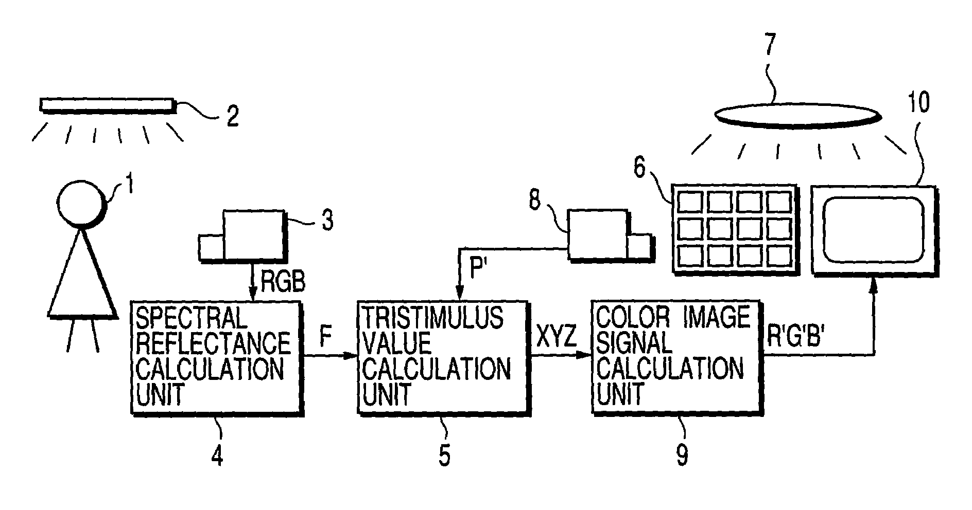
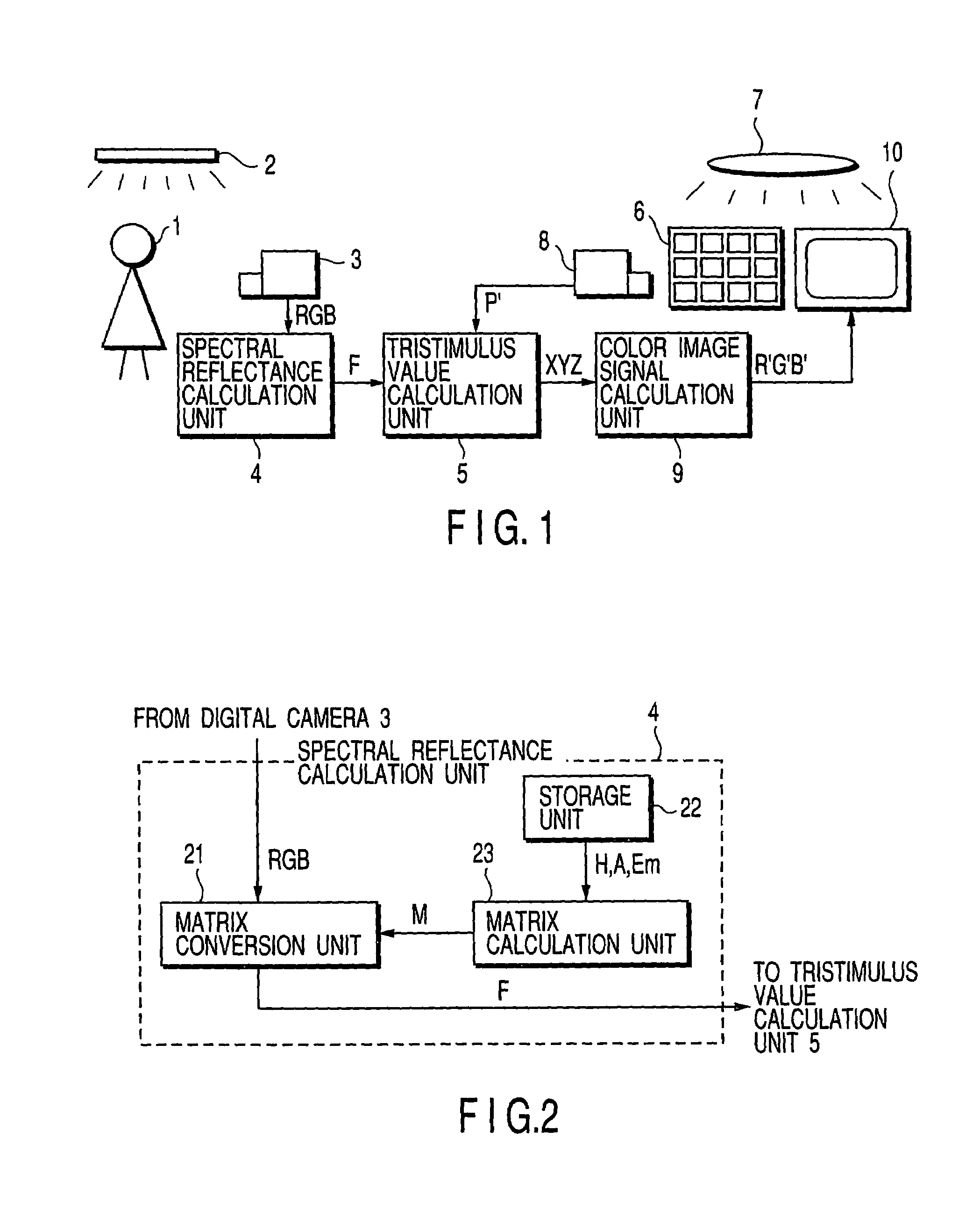
[0047]FIG. 1 shows a color reproduction system according to the first embodiment of the present invention.

[0048]When an object 1 is sensed by a first digital camera 3 under sensing illumination light by sensing illumination 2, an object image signal is output from the digital camera 3 as RGB image data. This RGB image data is input to a spectral reflectance calculation unit 4.

[0049]Upon receiving the RGB image data from the digital camera 3, the spectral reflectance calculation unit 4 calculates, as a spectral reflectance f(λ) corresponding to each pixel of the RGB image data, the spectral reflectance f(λ) of the object 1 using the spectral sensitivity data of the digital camera 3, spectrum data of the sensing illumination light, statistic data of the object spectral reflectance, and color matching function data.

[0050]Image data (called spectral reflectance image data) F corresponding to the calculated distribution of the spectral reflectance f(λ) is output. The spectral reflectance...

second embodiment

[0089]FIG. 5 shows a color reproduction system according to the second embodiment of the present invention.

[0090]In this embodiment, the output from a spectral reflectance calculation unit 14 becomes the expansion coefficient when the spectral reflectance of an object 1 is represented as the linear sum of basis functions. The arrangement of this embodiment is the same as that described in the first embodiment except the spectral reflectance calculation unit 14 and tristimulus value calculation unit 15, and a detailed description thereof will be omitted.

[0091]The spectral reflectance calculation unit 14 receives RGB image data from a digital camera 3 and outputs expansion coefficient data K when the spectral reflectance of the object 1 is represented by the linear sum of basis functions by using the spectral sensitivity data of the digital camera 3, spectrum data of sensing illumination light, and statistic data of the spectral reflection of the object 1.

[0092]The expansion coefficie...


PUM


Abstract

A color reproduction system includes a tristimulus value calculation unit for calculating tristimulus values (X, Y, Z) under observation illumination light corresponding to the spectral reflectance of an object, which is obtained by a spectral reflectance calculation unit, and a color image signal calculation unit for calculating output color image signals (R′, G′, B′) to a CRT monitor on the basis of the tristimulus values (X, Y, Z). The tristimulus value calculation unit converts spectral reflectance image data (F) of the object into tristimulus value image data (X, Y, Z) under the observation illumination light using the spectral reflectance data of a color chip formed from a plurality of unit color chips, color chip image data (P′) obtained by sensing the color chip with a digital camera under the observation illumination light, spectral sensitivity data of the digital camera, and color matching function data.

Description

CROSS-REFERENCE TO RELATED APPLICATIONS[0001]This application is based upon and claims the benefit of priority from the prior Japanese Patent Application No. 11-144932, filed May 25, 1999, the entire contents of which are incorporated herein by reference.BACKGROUND OF THE INVENTION[0002]The present invention relates to a reproduction system having a color image processing apparatus for calculating tristimulus values under observation illumination light corresponding to the spectral reflectance of an object.[0003]In recent years, color management systems (CMS) for matching the colors of input / output images between a plurality of color image devices such as a color CRT monitor and color printer are becoming popular in various fields handling color images.[0004]In a CMS, a problem is arisen in accurately reproducing colors to be perceived when sensing illumination light in sensing an object is different from observation illumination light in observing an image obtained by displaying im...

Claims


Application Information

Patent Timeline
IPC IPC(8): H04N9/64G06T1/00H04N1/46H04N1/60H04N9/67H04N17/02
CPCH04N1/6055H04N1/6086H04N1/6088H04N9/67
Inventor OHSAWA, KENRO
Owner OLYMPUS CORP
Why Eureka
Try Eureka