Iris diaphragm device

a technology of iris and diaphragm, which is applied in the field of iris diaphragm devices, can solve the problems of extreme unsuitability for microscopy, and achieve the effect of little installation spa

Active Publication Date: 2005-12-27
LEICA MICROSYSTEMS CMS GMBH
View PDF10 Cites 2 Cited by
  • Summary
  • Abstract
  • Description
  • Claims
  • Application Information

AI Technical Summary

Benefits of technology

[0006]It is therefore an object of the present invention to provide an iris diaphragm device that can be completely closed and that simultaneously exhibits a single defined diaphragm plane for applications in microscopy. At the same time, the new iris diaphragm device is intended to require little installation space and to be inexpensive.

Problems solved by technology

This proves, however, to be extremely unsuitable for microscopy, in which a single defined diaphragm plane is necessary.

Method used


Image

  • Iris diaphragm device
  • Iris diaphragm device
  • Iris diaphragm device

Examples


Embodiment Construction

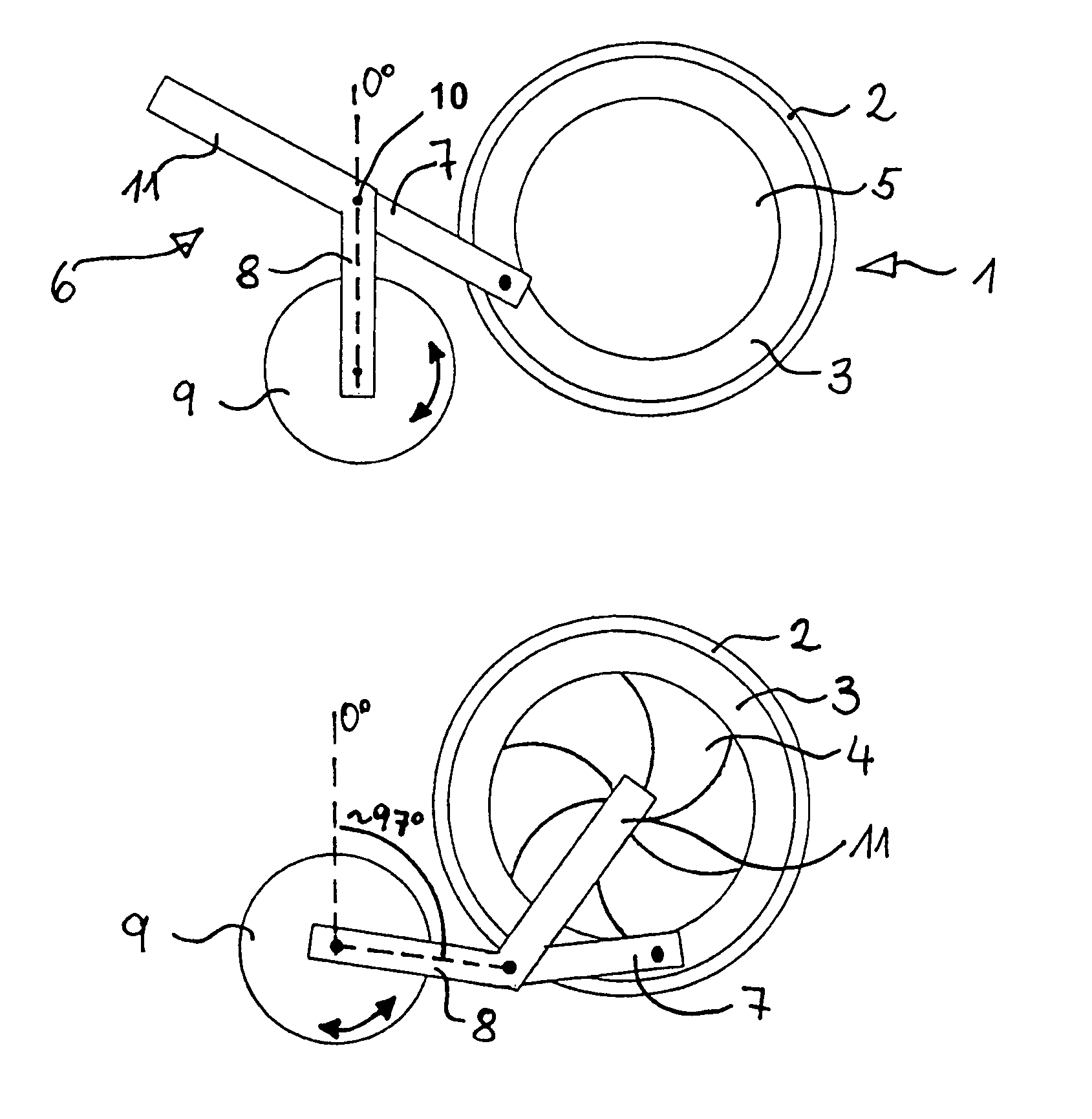
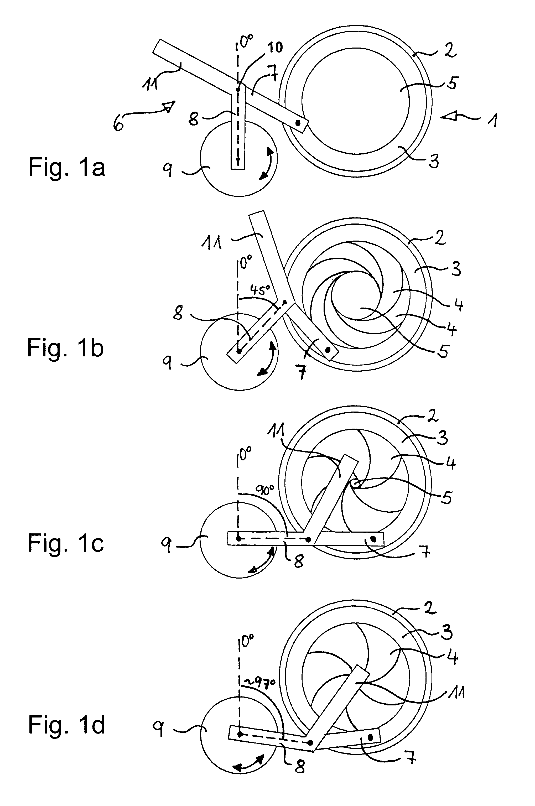
[0024]FIG. 1a shows an iris diaphragm device having an iris diaphragm 1. The latter has a stationary mount ring 2, a rotatable adjusting ring 3, and a number of blades 4 (concealed in the illustration). At the center of iris diaphragm 1, blades 4 leave open a diaphragm opening 5 that is steplessly adjustable between a maximum opening and a minimum opening. In the setting of the iris diaphragm device depicted here, actuation element 9 is in a position defined as the zero-degree position. A corresponding zero-degree axis through the rotation axis of actuation element 9 is shown in the Figure. In the position of coupling linkage 6 thus defined, diaphragm opening 5 corresponds to the maximum opening. Blades 4 are therefore concealed by adjusting ring 3 in this Figure.

[0025]In order to effect adjustment of diaphragm opening 5, a coupling linkage 6 engages on iris diaphragm 1. Coupling linkage 6 has at least two levers, of which one is mounted rotatably on rotatable adjusting ring 3 and o...


PUM


Abstract

An iris diaphragm device for a microscope includes an iris diaphragm having a stationary mount ring, a rotatable adjusting ring, and a plurality of blades. The plurality of blades form a diaphragm opening, which is steplessly adjustable, by rotation of the adjusting ring, between a maximum and a minimum opening size. A coupling linkage is connected to the adjusting ring and includes two levers. An actuation element drives the coupling linkage. A closure element is arranged on one of the levers in a way such that after a predefined size of the diaphragm opening has been established, a further actuation of the actuation element causes the closure element to pivot and cover the diaphragm opening.

Description

[0001]This application claims priority to German patent application DE 103 09 340.0, the subject matter of which is hereby incorporated by reference herein.[0002]The invention concerns an iris diaphragm device for a microscope, having an iris diaphragm that has a stationary mount ring, a rotatable adjusting ring, and a number of blades in a single diaphragm plane, so that by rotation of the adjusting ring, a diaphragm opening left open by the blades is adjustable steplessly between a maximum opening and a minimum opening.BACKGROUND[0003]Iris diaphragm devices of the kind cited above serve to regulate the beam cross section in optical instruments, for example in microscopes. The arrangement of the blades is implemented so that their one end is in each case rotatably supported on the annular mount, and their other end is in each case attached to the adjusting ring. As a result, the blades can be introduced as desired into the beam path by rotation of the adjusting ring, a central open...

Claims


Application Information

Patent Timeline
Patent Type & Authority Patents(United States)
IPC IPC(8): G02B21/24G02B5/00G02B21/06G03B9/02G03B9/06G03B9/22
CPCG02B5/005G02B21/06G03B9/22
Inventor BAMBERGER, STEFANWEISS, ALBRECHT
Owner LEICA MICROSYSTEMS CMS GMBH
Why Eureka
Try Eureka