

Reception apparatus
- Summary
- Abstract
- Description
- Claims
- Application Information
AI Technical Summary
Benefits of technology
Problems solved by technology
Method used
Image

Examples
first embodiment
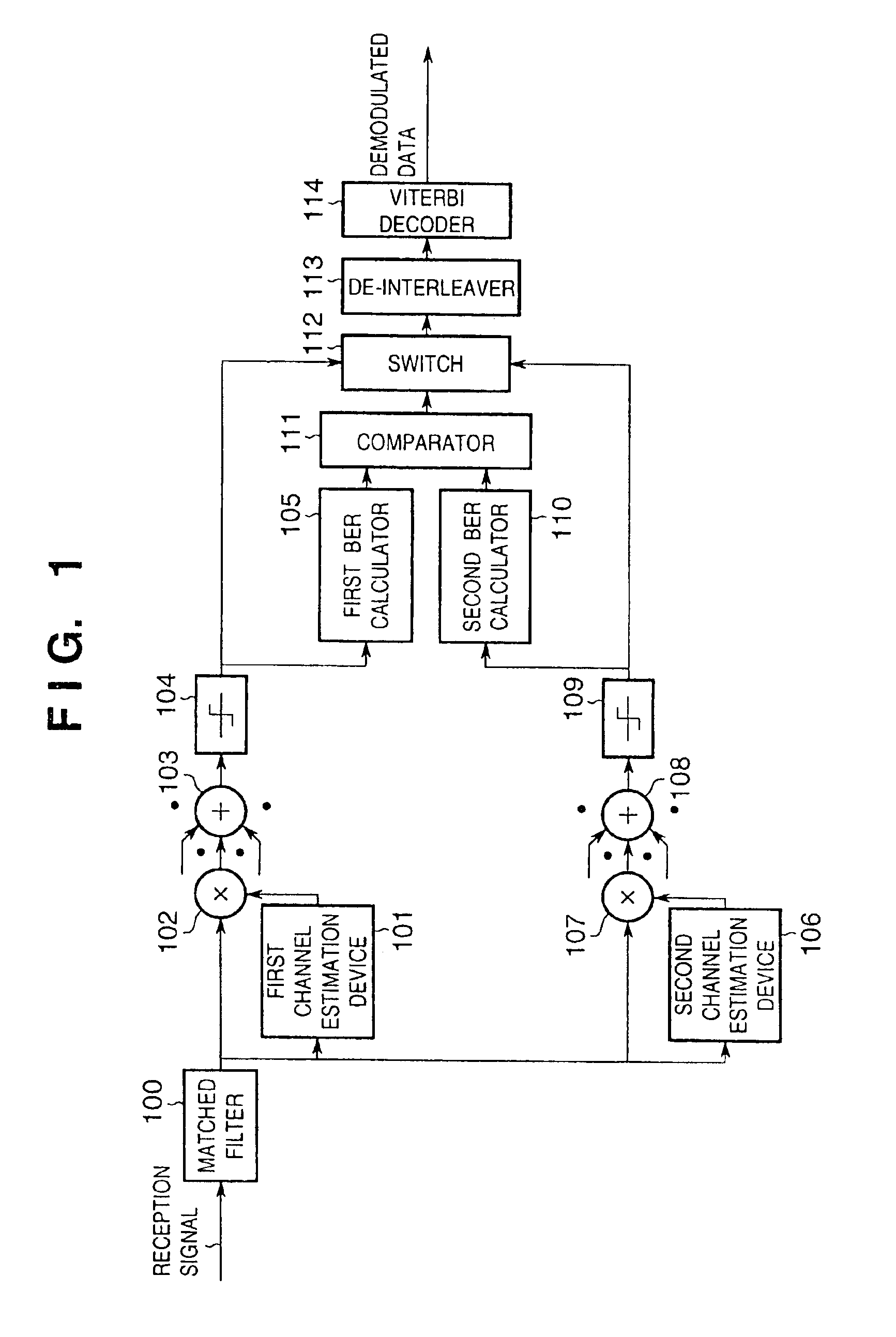
[0030]the present invention will be described first with reference to FIGS. 1 to 3.
[0031]FIG. 1 is a block diagram showing the arrangement of a RAKE reception apparatus according to this embodiment. Referring to FIG. 1, a reception signal is de-spread by a matched filter 100. The de-spread signal is input, in units of paths, to a first channel estimation device 101 to which a primary interpolation method is applied, and a channel estimation amount at a data symbol point is calculated. The conjugate complex number of the calculated channel estimation value is calculated. This value is multiplied by the output from the matched filter 100 by a first multiplier 102. The products obtained in units of paths are subjected to delay compensation and combined at a maximum ratio by a first RAKE combiner 103. The resultant data is converted into a bit stream by a first symbol decision device 104. A BER (Bit Error Rate) is obtained by a key input section 105 from a known pilot symbol (FIG. 7) an...
second embodiment
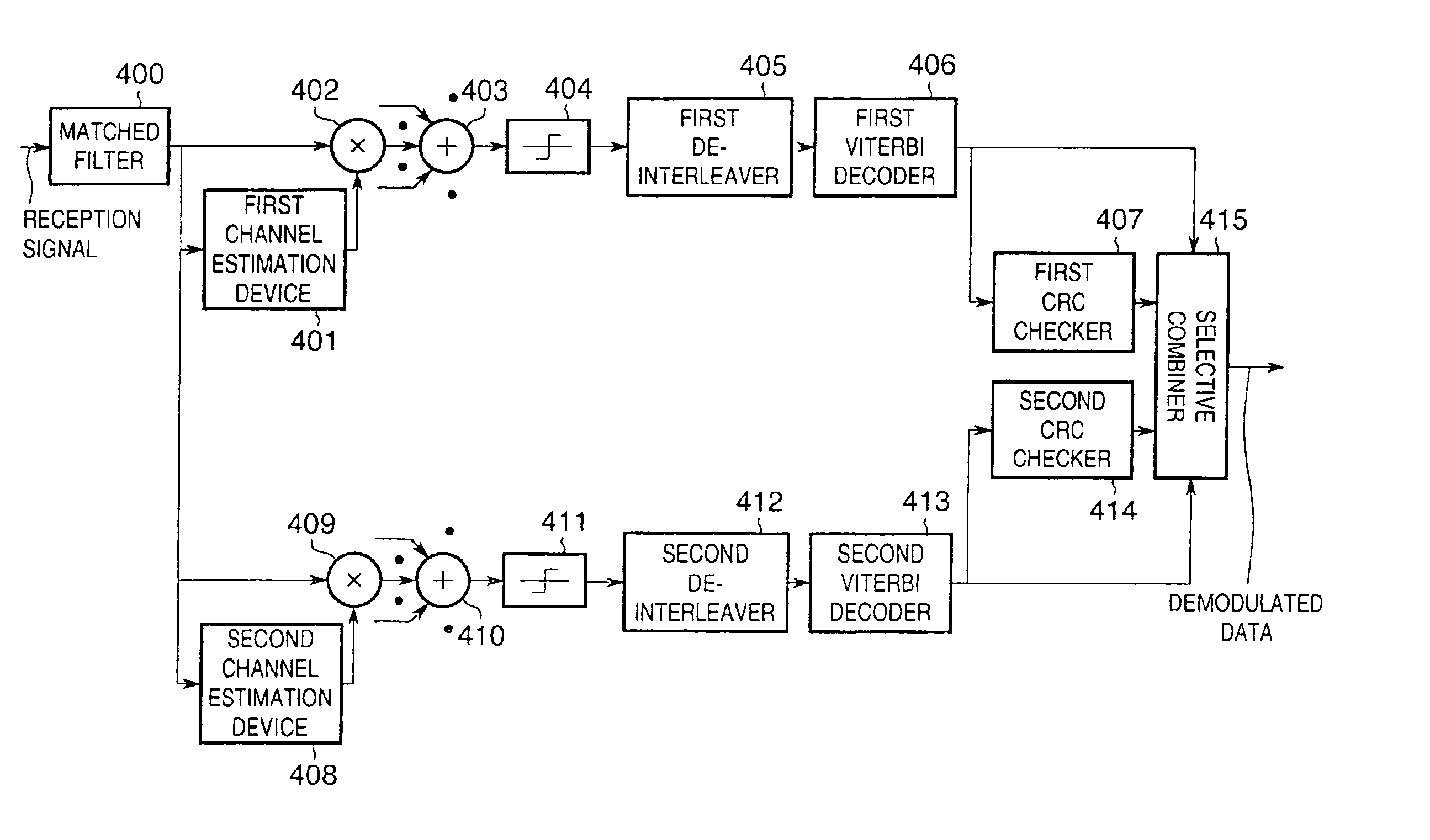
[0036]the present invention will be described next with reference to FIG. 4.
[0037]FIG. 4 is a block diagram showing the arrangement of a RAKE reception apparatus-according to this embodiment.
[0038]In the reception apparatus of this embodiment, the frame format shown in FIG. 7 is used. In this embodiment, however, a CRC is added to a data symbol to be transmitted. That is, each frame consists of a pilot symbol, a data symbol, and a CRC for frame error detection.
[0039]Referring to FIG. 4, a reception signal is de-spread by a matched filter 400. The de-spread signal is input, in units of paths, to a first channel estimation device 401 to which the primary interpolation method is applied, and a channel estimation amount at a data symbol point is calculated. The conjugate complex number of the output channel estimation value is calculated. This value is multiplied by the output from the matched filter 400 by a first multiplier 402. The products obtained in units of paths are subjected to...
third embodiment
[0043]the present invention will be described first with reference to FIGS. 5 and 6.
[0044]FIG. 5 is a block diagram showing the arrangement of a RAKE reception apparatus according to this embodiment. Referring to FIG. 5, a reception signal is de-spread by a matched filter 500. The de-spread signal is input, in units of paths, to a first channel estimation device 501 to which the primary interpolation method is applied, and a channel estimation amount at a data symbol is calculated. The conjugate complex number of the calculated channel estimation value is calculated. This value is multiplied by the output from the matched filter 500 by a first multiplier 502. The products obtained in units of paths are subjected to delay compensation and combined at a maximum ratio by a first RAKE combiner 503. Symbol decision is made by a first symbol decision device 504. The output from the first RAKE combiner 503 and the decision result from the first symbol decision device 504 are input to a fir...
PUM
 Abstract
Description
Claims
Application Information