Fiber optic peep sight

Inactive Publication Date: 2006-01-03
STRATHMAN DAVID MICHAEL
View PDF19 Cites 38 Cited by
  • Summary
  • Abstract
  • Description
  • Claims
  • Application Information

AI Technical Summary

Benefits of technology

[0027](g) To provide a solid rubber coated peep sight embodiment enhancing peep sight bowstring security with rubberized gripping surface.
[0028]In accordance with the present invention is a generally horizontally mounted bowstring large aperture peep sight comprising side lit optic cross-piece elements, cross hair system centered within large peep sighting aperture opening secured within surrounding embodiment. Optic cross-piece elements, peep sight embodiment centrally located within bowstring axis provides an optical colored small center reference window in middle of large peep aperture for archers reference providing consistent and ease of forward sight pin centering within center of the large aperture style peep sight.
[0029]The novel features which are believed to be characteristic of the invention, both its organization and method of operation with further objective and advantages thereof, will be better understood from the following description and accompanying drawings in inventors preferred embodiment of the invention illustrated by way of example. It is to be expressly understood, however, that the drawings is for the purpose of illustration and description only and is not intended as a definition of the limits of the invention.

Problems solved by technology

These vertical bowstring mounted peep sights became ineffective with today's newer bows varied draw and axial lengths.
As can be seen, the traditional fore mentioned peep sights made improvement over the conventional peep sight problem with bow draw and axial length angles, however still peep sight aperture viewing remained limited to small peep aperture hole for target and large peep aperture hole for hunting.
Small peep sight aperture applications remain subject to visual target loss in medium to low light conditions typical outdoors and hunting in wooded terrain, leaving the hunter only to use a larger peep aperture application for better visual clarity and targeting visibility.
The problem presented with the larger peep aperture hole application designs is it now remains a contributing factor to loss of arrow accuracy with the archer failing to center forward sight pin in the center of the larger aperture peep sight hole.
However, the larger aperture peep providing improvement towards improved visibility during less than desirable light conditions, it remains a counter productive solution having to substitute the accuracy provided of the smaller peep aperture for the visibility provided that of the larger peep aperture design.
Thereafter, inventors created several types and designs of peep sights in effort in increase archers shooting accuracy but remained limited to specific peep hole sizes for each general application, that of small peep aperture size for target and large for hunting.
It is now with the larger aperture hunting peep sights a common problem presents itself with the best of archers having there arrow shot groupings falling apart.
This is because they are now posed to a greater challenge, the loss of accuracy provided by a small peep with increased difficulty of consistent centering of the forward sight pin in the (center) of the larger aperture peep hole.
This problem is obviously seen more prevalent with the larger aperture 3D and hunting larger styled aperture peep sights.
Overall, there are few singular peep sight designs and available on the market to accommodate the need of both visibility and accuracy, but not without required changes and or adjustments of peep aperture diameter size.
Both above fail to provide unobstructed viewing subject bow draw and axial lengths as well elements subject to freezing in inclement field weather conditions.
However, application of dividing bowstring among three slots creates obstruction with bowstring in archers visual targeting through peep sight aperture.
Problems with this design is the close proximity of archers eye with field of vision subjective to flare or blooming from fiber light collecting ends creating distortion of forward sight pin effecting visual alignment and thus accuracy.
Additionally, problems with being vertically mounted as fore mentioned with prior art references.
Nevertheless, all bowstring mounted peep sights heretofore known suffer from a number of disadvantages:(a) Peep sight aperture hole is too small and field of vision is obstructed and lost during low lighting condition making it insufficient for archery hunting field conditions.(b) Peep sight aperture hole is large for hunting application however arrow grouping and accuracy is lost with inconsistent forward sight pin centering within large peep aperture.(c) Peep sight bowstring mounting and peep aperture hole does not properly align with various archers draw and bow axial lengths at full draw and viewing position.(d) Adjustable peep sight aperture's peep size disc, insert or slide needs changing from one application to the other.
Mechanical adjustable parts within embodiment are subject to the weather elements snow and ice with possible parts becoming frozen, dislodged, displaced or lost.(e) Fiber optic light collecting fiber (ends), cause blooming or flare within close visual eye proximity at full draw thus causing difficulty sighting forward sight pin and target alignment.

Method used


Image

  • Fiber optic peep sight
  • Fiber optic peep sight
  • Fiber optic peep sight

Examples


Embodiment Construction

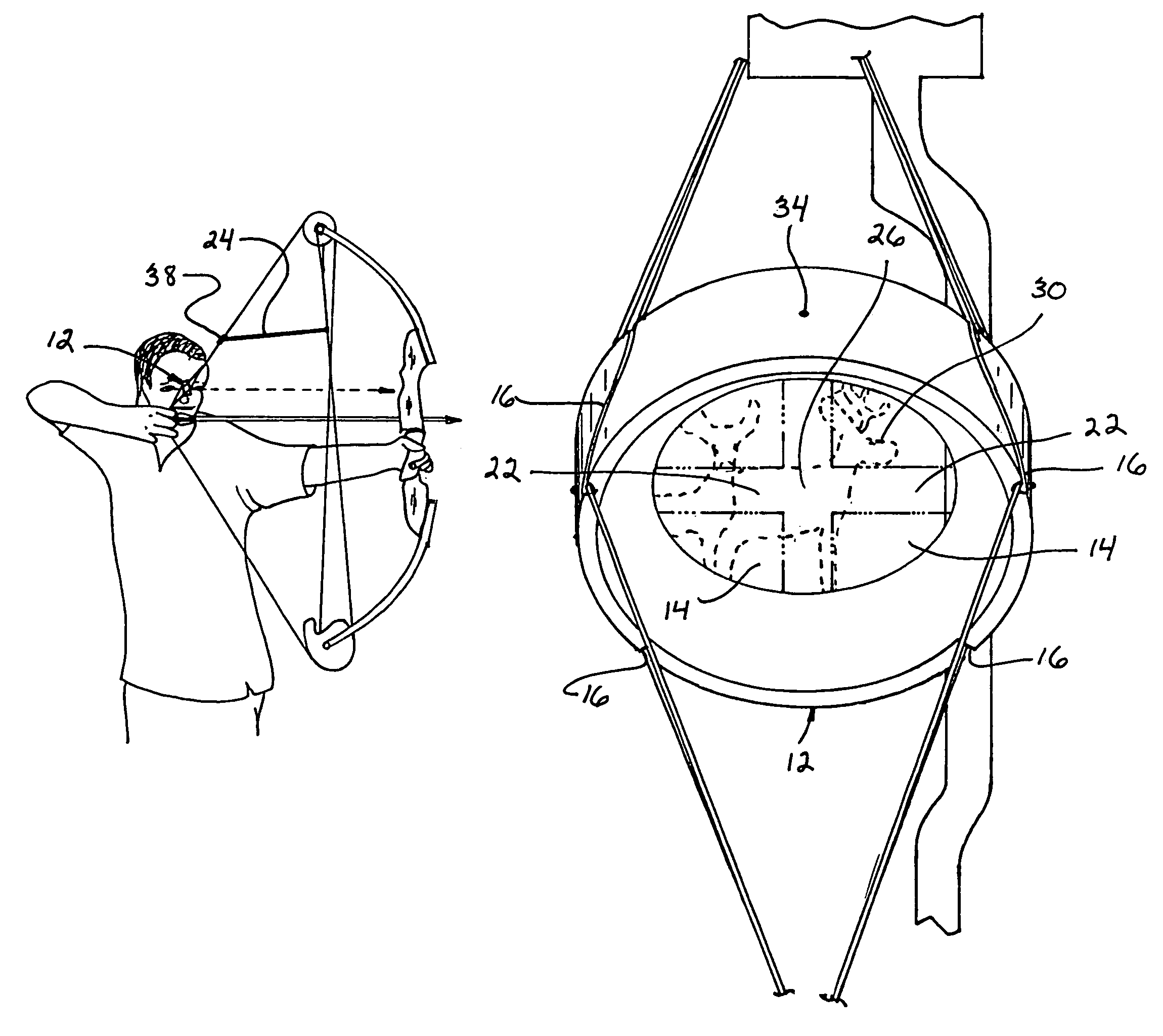
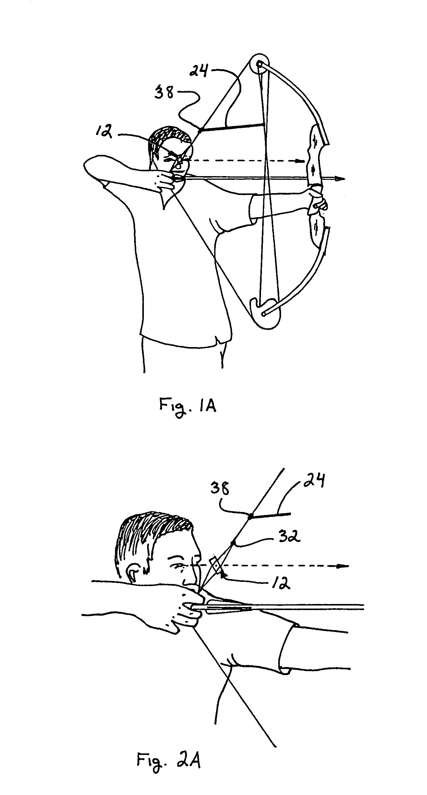
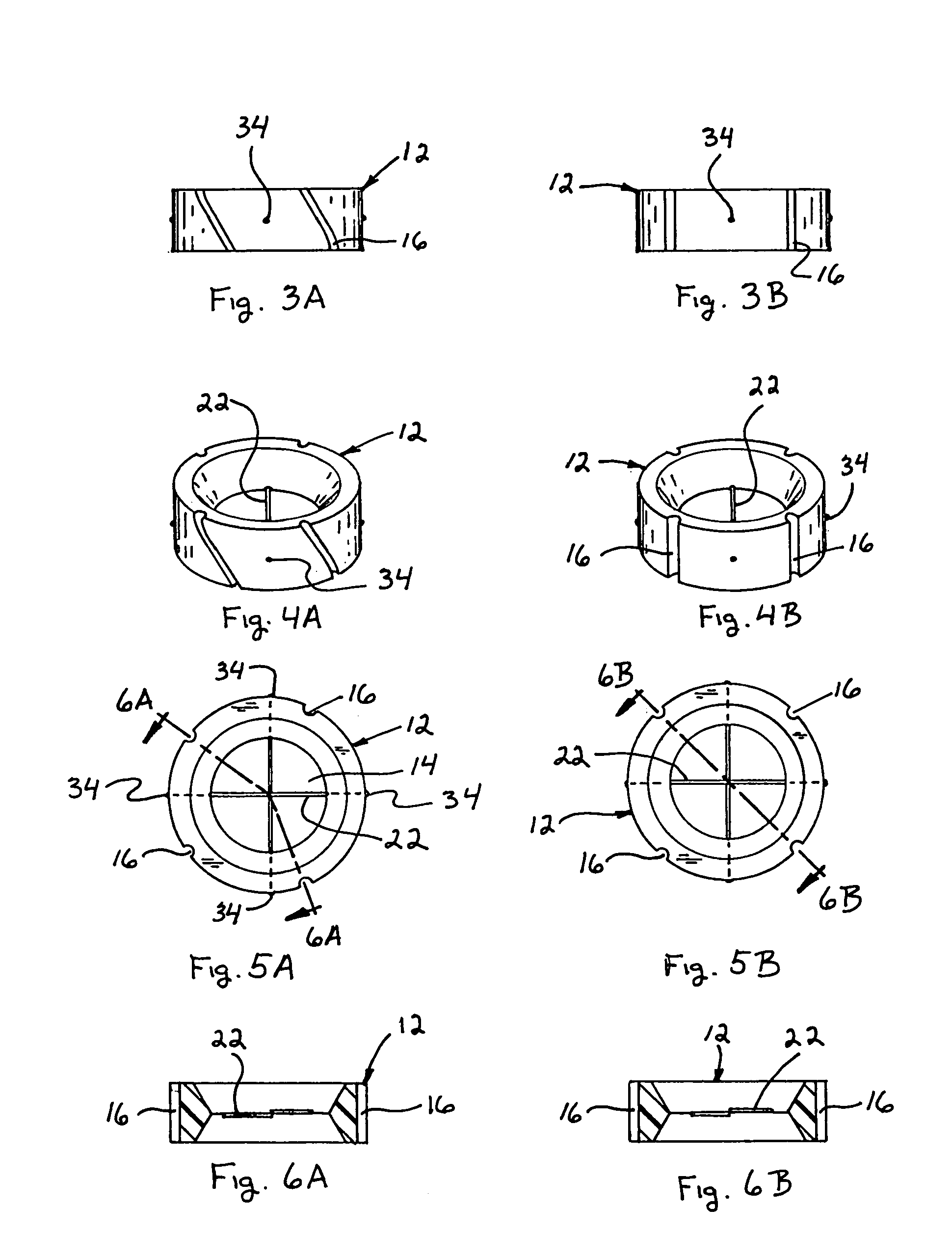
[0047]A preferred embodiment of the present fiber optic peep is illustrated in FIG 1A though FIG. 11A. An understanding of the present invention can be readily gained by reference to FIG. 1A and FIG. 2A wherein side elevation views of the optic peep sight 12 mounted generally horizontal and canted 30 degrees in a multi-strand bowstring is shown. In FIG. 1A and FIG. 2A the archer has drawn the bowstring and it can further be seen the line of the bowstring axis, center peep sight aperture 14, optic cross-pieces 22 intersecting point are the same which can further be seen and illustrated FIG. 9A. In FIG. 2A the archer has drawn the bowstring in the full cocked and release position. In FIG. 2A the bowstring is drawn in full user cocked position, positioning optic peep sight 12 upward towards the archer such that it now becomes generally a vertical plane position permitting archer to view through peep sight aperture 14 across optic cross-pieces 22 illustrated in FIG. 10A and FIG. 11A.

[00...


PUM


Abstract

An improved bowstring mounted peep sight used in archery improving archer's accuracy. The present invention preferred embodiment having a body generally horizontal within bowstring axis has through the body centrally located luminous color optic cross-pieces indexing the center of the peep sight aperture. The characteristic of the present invention optic cross-pieces fiber side lit attenuation allows the archer to easily see through the large aperture peep sight aligning forward bow sight pin on color cross-pieces sectional center aperture small highlighted index reference window. Small reference index window cross hair center provides consistent centering reference within the large aperture by proximal blur designed within Fiber Optic Peep Sight. A second characteristic is both peep sight embodiment and optic cross-piece fibers be further enhanced with florescent light collecting glow pigment, dyes or other color illuminating materials for increased viewing during less than desirable lighting conditions.

Description

BACKGROUND OF THE INVENTION[0001]1. Field of the Invention[0002]This invention relates to a bowstring mounted archery peep sight, specifically an improved designed peep aperture with a fiber optic cross hair.[0003]2. Description of Related Art[0004]Bowstring mounted peep sights enable the archer to sight his or her shot viewing through the peep sight open aperture. It is convenient for the archer to sight his forward sight pin within the center of said aperture opening for a more readily consistent and accurate shot. The method and design of bowstring mounted peep sights generally split the center of the bowstring axis allowing the archer to view through the string verse through the blur of the string without such mounted peep sight.[0005]Therefore, early conventional bowstring peep sights where vertically mounted in bowstring axis. This design can be referred in U.S. Pat. No. 3,199,502 (1965) to Opal and U.S. Pat. No. 3,703,771 (1975) to Saunders. These vertical bowstring mounted p...

Claims


Application Information

Patent Timeline
Patent Type & Authority Patents(United States)
IPC IPC(8): F41G1/467
CPCF41G1/467F41G1/08F41B5/1419
Inventor STRATHMAN, DAVID MICHAEL
Owner STRATHMAN DAVID MICHAEL
Why Eureka
Try Eureka