
Recoil starter

a starter and coil technology, applied in the direction of engine starters, muscle operated starters, machines/engines, etc., can solve the problems of damper spring breakage and unpleasant feeling during startup, and achieve the effect of improving damper spring durability, inhibiting excessive deformation of damper springs, and enhancing durability

Inactive Publication Date: 2006-01-03
STARTING IND CO LTD
View PDF5 Cites 25 Cited by
  • Summary
  • Abstract
  • Description
  • Claims
  • Application Information

AI Technical Summary

Benefits of technology

The design enhances damper spring durability, absorbs startup shocks effectively, and allows for increased shock-absorbing capabilities without scaling up the recoil starter's size, providing a smoother startup experience and preventing cam breakage.

Problems solved by technology

Under such a condition, the bent portions at the opposite ends of the damper spring 34 undergo an excessive stress, possibly resulting in breakage of the damper spring 34.
In this technique, however, when the stopper means operates, a feel of collision is caused and transmitted as a shock to the operator's hand pulling the recoil rope 39, resulting in an unpleasant feel during startup.

Method used


Image

  • Recoil starter
  • Recoil starter
  • Recoil starter

Examples


Embodiment Construction

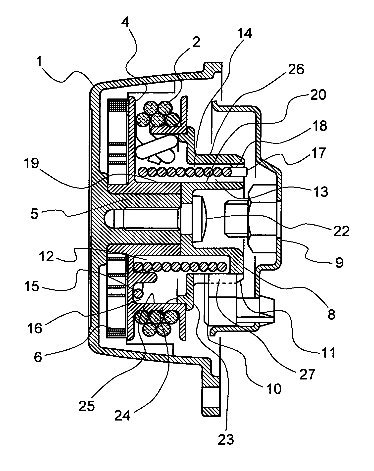
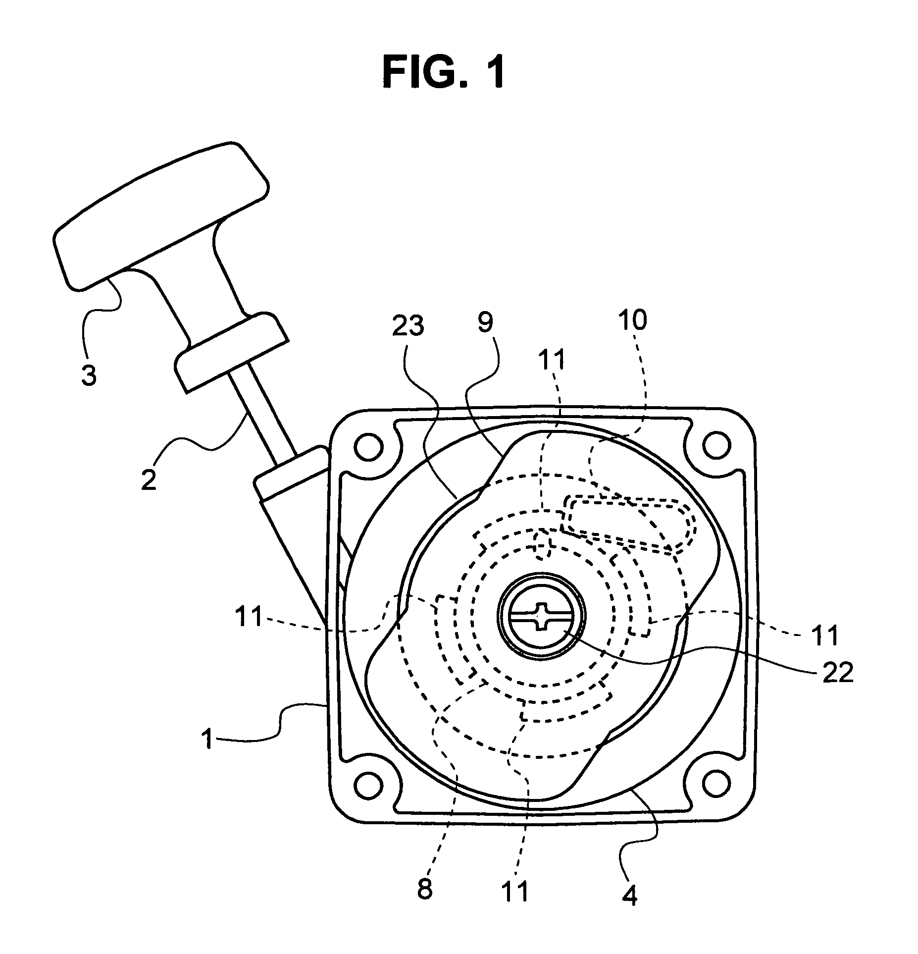
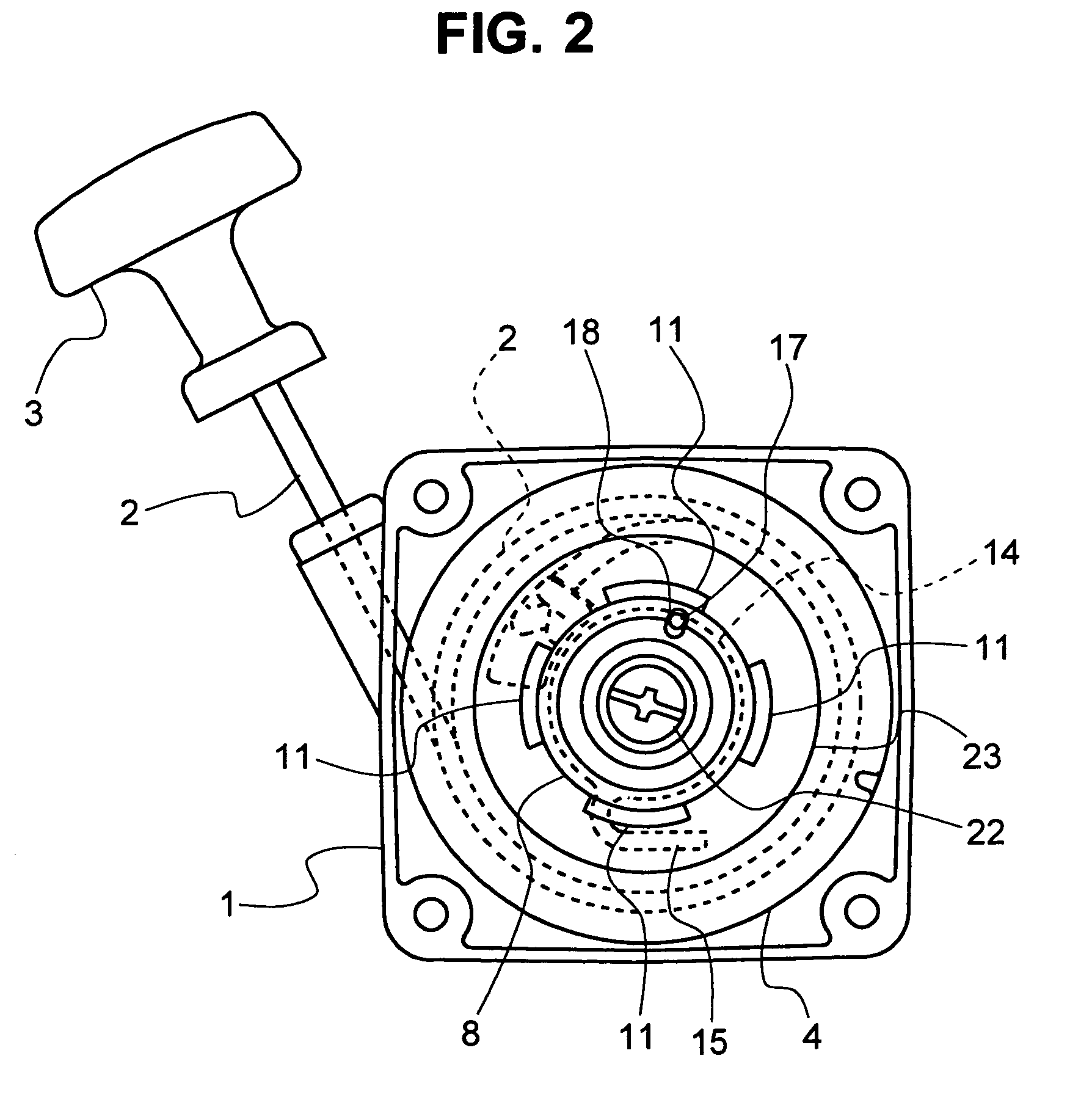
[0029]A preferred embodiment of the present invention will now be described with reference to the drawings. A recoil starter according to the embodiment of the present invention, as shown in FIG. 1, is constructed such that when a handle 3 which is joined to one end of a recoil rope 2 exposed outside a casing 1 is pulled, a rope reel 4 received within the casing 1 is rotationally driven and thus a cam 8 is rotated by the rope reel 4, so that a rotational member 9 coupled to a crankshaft of an engine via a ratchet mechanism 10 which is engageable with cam pawls 11 formed on an outer peripheral surface of the cam 8, to thereby start the engine.

[0030]As shown in FIGS. 2 and 3, the rope reel 4 has the recoil rope 2 wound therearound, of which the one end is drawn outside the casing 1, and is rotatably supported by a reel shaft 5 which is integrally formed on an inside of the casing 1 in a manner to be protruded inwardly in the casing 1. The other end of the recoil rope 2 wound around th...


PUM


Abstract

A recoil starter having improved durability by inhibiting excessive deformation of a damper spring, and capable of receiving a damper spring with high shock-absorbing and force-storing capabilities. The recoil starter includes a rope reel and a cam which are rotated by pulling a recoil rope, so that a rotation of the cam is transmitted to an engine via a ratchet mechanism to start the engine. A damper spring which couples the rope reel and the cam to each other has, at opposite ends thereof, engaging portions radially movably supported by holding portions of the rope reel and the cam, respectively, so that substantially the overall length of the damper spring winds and tightens uniformly around outer peripheral surfaces of both bosses of the rope reel and the cam due to a startup resistance of the engine.

Description

BACKGROUND OF THE INVENTION[0001]1. Field of the Invention[0002]The present invention relates to a recoil starter having a recoil rope wound around a rope reel, wherein one end of the recoil rope drawn outside a casing of the recoil starter is pulled to rotate the rope reel so that a rotational force of the rope reel is transmitted to a cam via a damper spring, and then a rotation of the cam is transmitted to a rotational member coupled to a crankshaft of an engine via a ratchet mechanism to rotate the rotational member, whereby the engine is started.[0003]2. Description of the Related Art[0004]Among recoil starters designed to transmit a rotation of a rope reel, rotated by pulling a recoil rope, to a cam and further rotate a rotational member such as flywheel magnet or drive pulley via a centrifugal clutch or other ratchet mechanism which engages with or disengages from the cam, a recoil starter has been proposed which is constructed to absorb a shock, caused due to fluctuations in...

Claims


Application Information

Patent Timeline
Patent Type & Authority Patents(United States)
IPC IPC(8): F02N3/02F02N5/02
CPCF02N3/02F02N5/02Y10T74/134
Inventor TSUNODA, SHUHEITOHYAMA, ISAOMORISHIGE, TOSHINORI
Owner STARTING IND CO LTD
Learn More