Wire sawing process and device

a wire sawing and wire technology, applied in metal sawing machines, stone-like material working machines, grinding machines, etc., can solve problems such as frequent rejection

Inactive Publication Date: 2006-01-03
APPLIED MATERIALS SWITZERLAND
View PDF11 Cites 9 Cited by
  • Summary
  • Abstract
  • Description
  • Claims
  • Application Information

AI Technical Summary

Benefits of technology

[0008]The present invention has for its object to overcome the mentioned drawbacks, and a process according to the present invention is characterized by the fact that the piece or pieces to be sawed are fixed on the support table such that one of the prismatic surfaces of this piece directed toward the layer of wires, forms a predetermined inclination with said working plane along a line of intersection parallel to the

Problems solved by technology

During the start of sawing, it has thus been noted that the wires of the layer of wires slide on the surface and have the tendency to group themselves two by tw

Method used


Image

  • Wire sawing process and device
  • Wire sawing process and device
  • Wire sawing process and device

Examples


first embodiment

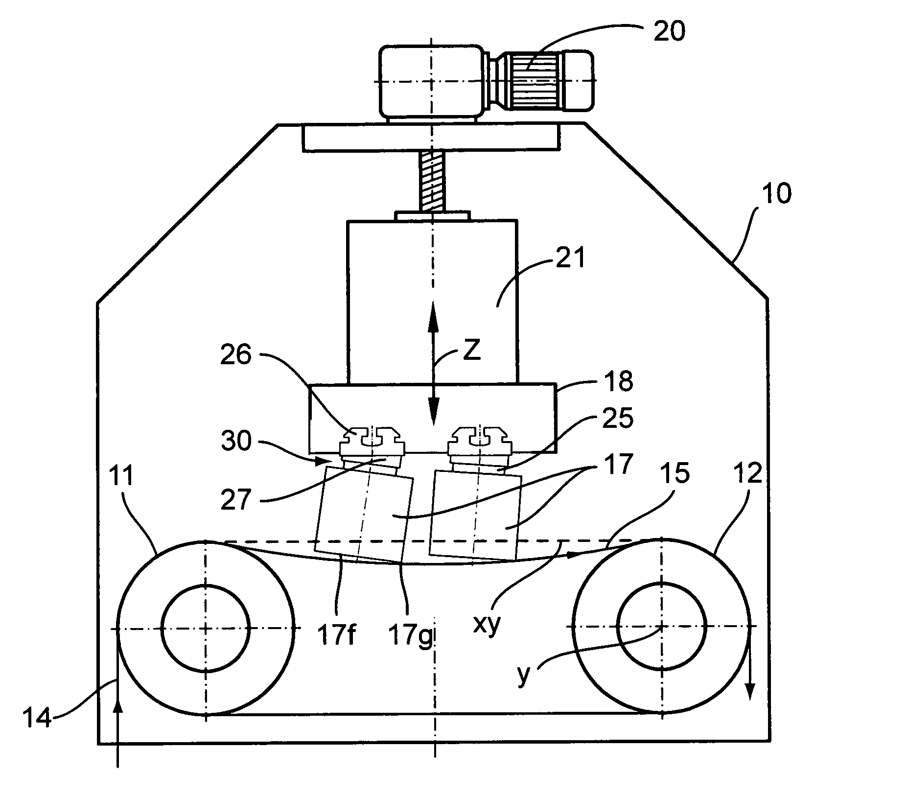
[0020]With reference to FIGS. 1, 2a and 2b, the sawing device comprises a frame 10 and wire guide cylinders 11, 12, here two in number, mounted on this frame with their axes disposed parallel to each other given of course that the device could have more than two wire guide cylinders, for example four.

[0021]The wire 14 is unrolled from a supply bobbin (not shown) and then wound about the wire guide cylinders to form at least one layer 15 of parallel wires in a sawing region. The wire is then recovered in a suitable device (not shown), such as a receiving bobbin or a recovery vat.

[0022]One, two or more pieces 17 to be sawed, such as ingots of a hard material, are mounted on a support table 18.

[0023]These pieces to be sawed have an elongated prismatic form with a square, pseudo-square or rectangular base and four prismatic principal surfaces of which one, 17f, in the lower position, is directed toward the layer 15 of wires. The edges are sharp in the case of multi-crystalline pieces 1...

second embodiment

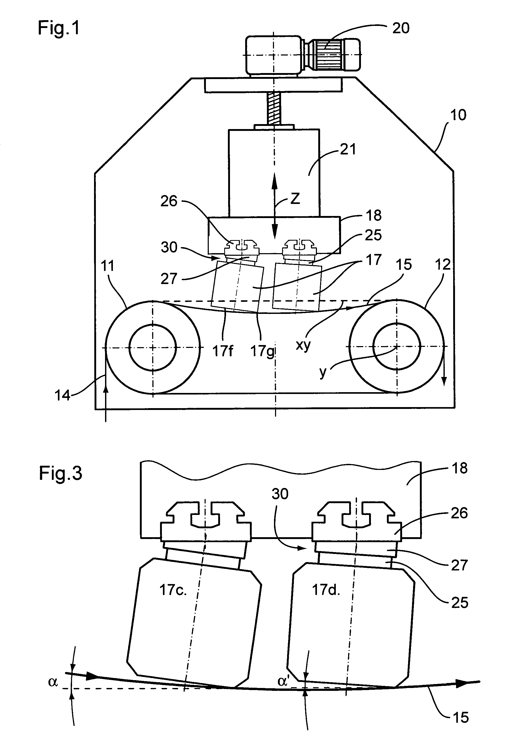
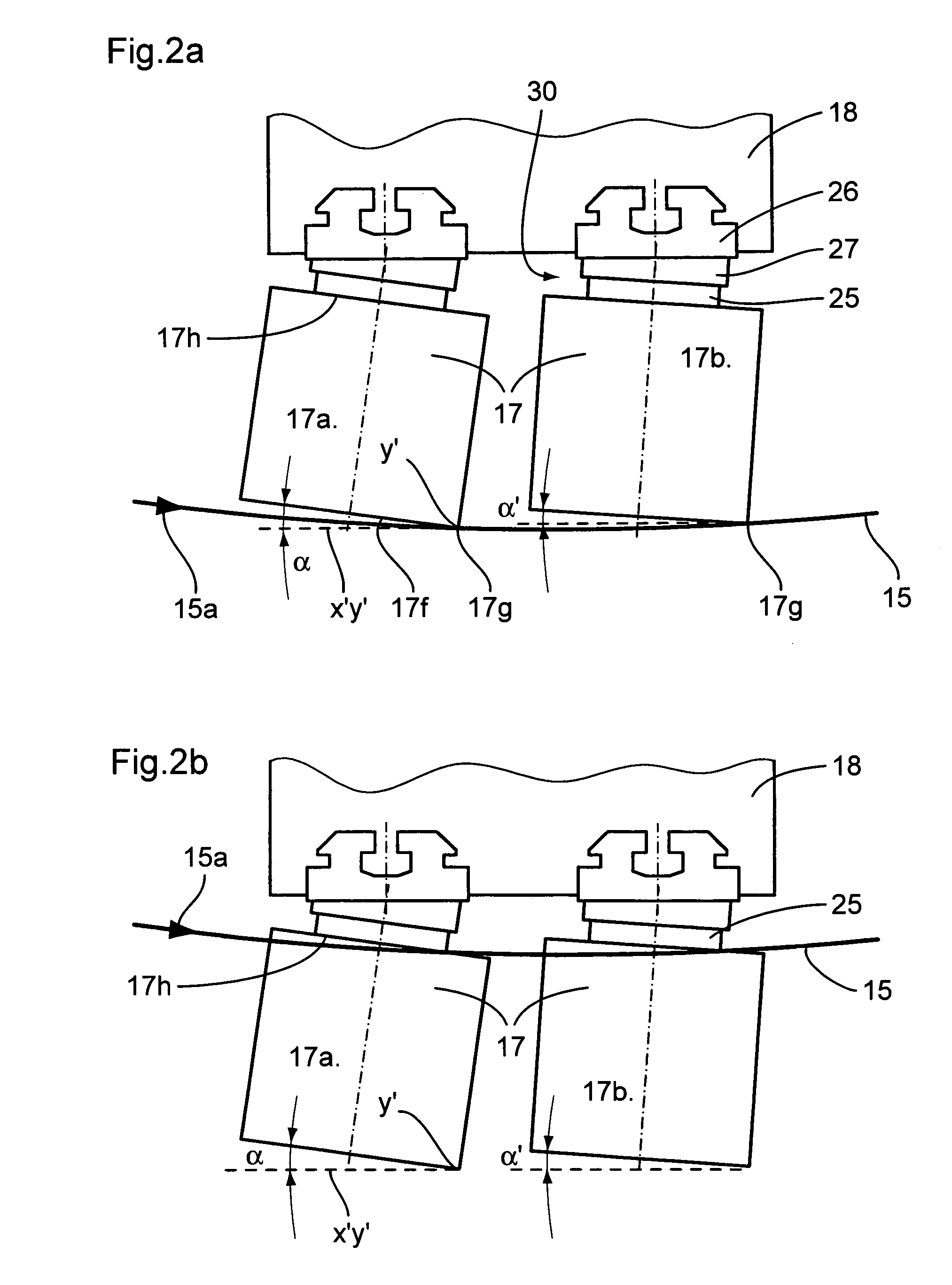
[0051]In the second embodiment shown in FIG. 9, the support table 18 also carries two pieces 17a and 17b to be sawed, by means of intermediate plates 25 and cementing plates 27. However, the wires of the layer 15 of wires in this case have an alternating back and forth movement.

[0052]The inclination members 30e are thus in this case arranged such that the angles of inclination α, and α″ open in opposite directions relative to each other. Thus, at the end of sawing, the slightly deflected layer of wires will be substantially parallel to the upper prismatic surfaces of the two pieces 17 to be sawed and it is thus avoided that the wires penetrate from the intermediate plate 25 toward the piece 17 to be sawed. The cut is thus without chipping up to the end of sawing.

[0053]The inclination members 30e are in this case constituted by two angular wedges 27e forming cementing plates 27. Other inclination members, for example pivotal members mounted on the support table 18 or the ingot holder...


PUM

PropertyMeasurementUnit
Angleaaaaaaaaaa
Angleaaaaaaaaaa
Angleaaaaaaaaaa

Abstract

In the sawing process and device according to the invention, the pieces to be sawed are mounted on at least one support table and caused to bear against a layer of wires. Inclination structure in the form of wedges or pieces for angular adjustment by pivoting and blocking, are provided to mount the pieces obliquely with angles of inclination between one of their prismatic surfaces and a horizontal working plane. There is thus obtained a precise beginning of sawing with sawed slices of equal thickness and a careful end of cutting without chipping.

Description

FIELD OF THE INVENTION[0001]The present invention relates to a wire sawing process comprising sawing at least one prismatic piece to be sawed with a substantially square or rectangular base, by means of at least one layer of wires stretched between at least two wire guide cylinders whose axes are parallel to a working plane and held in position by grooves provided on the surface of the wire guide cylinders which define the interval between the wires of the layer of wires, hence the thickness of the sawed slices, the wires of the layer being adapted to move with alternating or continuous motion whilst bearing against the piece or pieces to be sawed fixed on at least one support table by means of an intermediate plate, the sawing process being carried out with relative advancing movement between the piece to be sawed and the layer of wires.[0002]The invention also relates to a device for practicing the mentioned process.BACKGROUND OF THE INVENTION[0003]Wire sawing devices of the menti...

Claims


Application Information

Patent Timeline
IPC IPC(8): B23D57/00B28D5/00B24B27/06B28D5/04
CPCB28D5/0088B23D57/0046
Inventor MULLER, ANDREASBORTNIKOV, ALEXANDER
Owner APPLIED MATERIALS SWITZERLAND
Why Eureka
Try Eureka