Modular capillary pumped loop cooling system

a cooling system and capillary pump technology, applied in the direction of electrical apparatus casings/cabinets/drawers, electrical devices, semiconductor/solid-state device details, etc., can solve the problems of general restriction of heat sink use, poor heat sink efficiency, and inability to meet the needs of cooling engineers

Inactive Publication Date: 2006-01-03
INTEL CORP
View PDF53 Cites 61 Cited by
  • Summary
  • Abstract
  • Description
  • Claims
  • Application Information

AI Technical Summary

Problems solved by technology

The low profiles of the 1U and 2U form factors create several problems for thermal engineers.
Due to internal height limitations and airflow considerations, the use of heat sinks is generally restricted to lower profile heat sinks, which are much less efficient than the taller heat sinks discussed above.
Although heat sinks are advantageous in many inst...

Method used


Image

  • Modular capillary pumped loop cooling system
  • Modular capillary pumped loop cooling system
  • Modular capillary pumped loop cooling system

Examples


embodiment 80

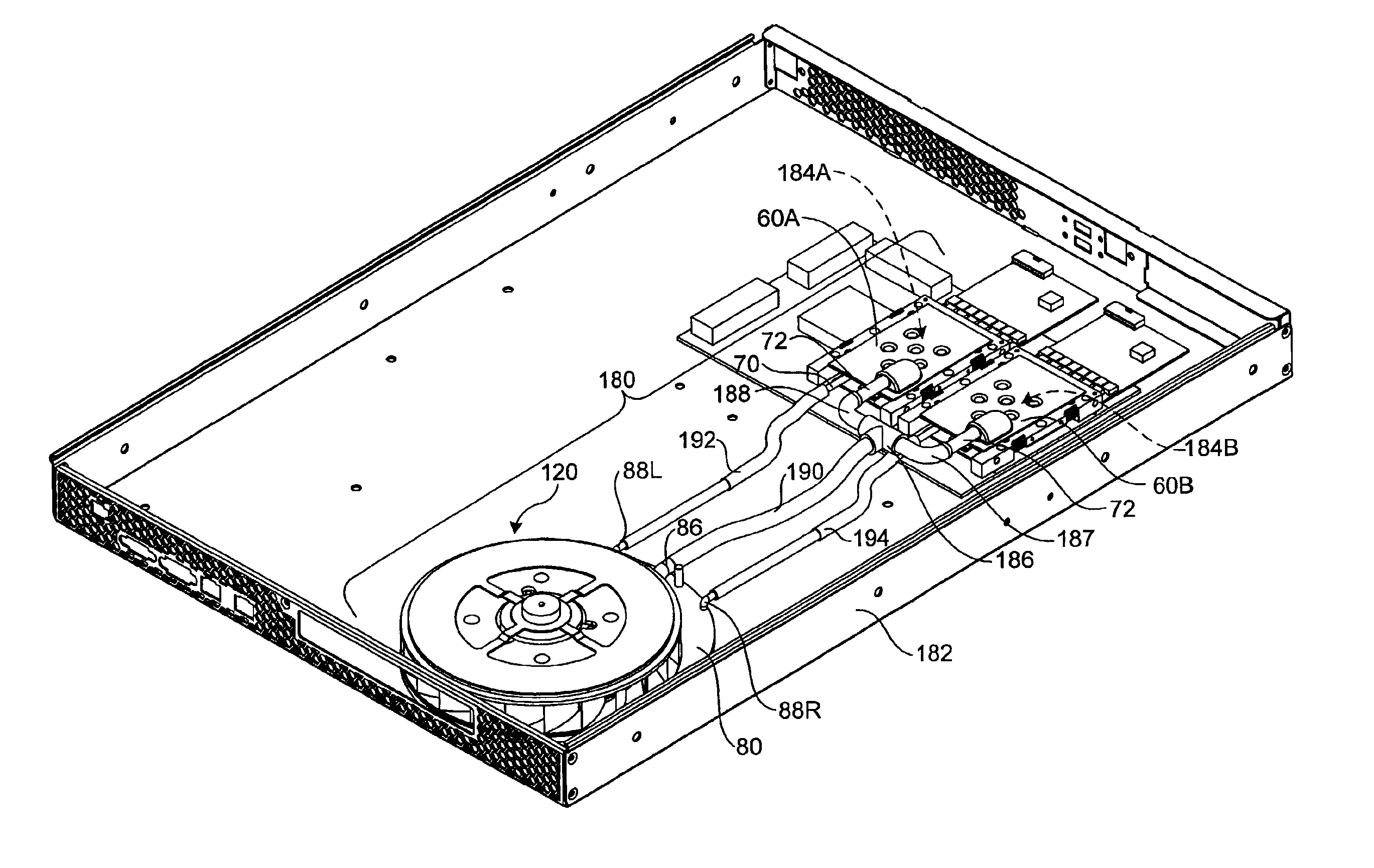
[0046]Details of a first exemplary condenser embodiment 80 are shown in FIGS. 4A-5D. Condenser 80 includes a channeled base member 82 over which a cover plate 84 is disposed upon assembly. Cover plate 84 includes a vapor inlet port 86, a pair of liquid outlet ports 88L and 88R, and a charging port 90. As shown in FIG. 4B, in one embodiment cover plate 84 includes a plurality of posts 92 that are used to strengthen the cover plate and prevent it from collapsing when condenser 80 is used in sub-atmospheric CPL systems. The posts also act as nucleation sites for condensate formation, by effectively conducting heat out of the condenser, and provide effective entrainment traps for the vapor flowing past them. Cover plate 84 further includes a hole 94 and a plurality of fastener clearance holes 96.

[0047]As shown in FIGS. 4A and 4D, channeled base member 82 includes a plurality walls that are configured to guide fluid condensed in a central condensing region of condenser 80 out through liq...

embodiment 140

[0054]A second exemplary condenser embodiment 140 is shown in FIGS. 6A and 6B. Condenser 140 includes a body 142 including a cavity 144 into which vapor enters through a vapor inlet port 146 and out of which liquid exits through a liquid outlet port 148. In one embodiment, a heatsink 150 including a plurality of fins 151 is integrated into body 142. Optionally, a heatsink may be attached to body 142 as a separate part. A cover 152, including an integrated heatsink 154 comprising a plurality of fins 155 is disposed over cavity 144 to form an enclosed volume upon assembly of the cover to body 142. Body 142 further includes a plurality of posts 156 for structural purposes in sub-atmospheric embodiments and nucleation enhancement.

[0055]As vapor 26 enters cavity 144 through vapor inlet port 146, it condenses into droplets on the walls in the upper portion of the cavity; eventually the droplets fall to the lower portion of the cavity to form liquid 32, which exits the cavity through liqui...

embodiment 160

[0056]A third exemplary condenser embodiment 160 is shown in FIGS. 7A and 7B. Condenser 160 comprises a single loop of tubing 162 having a helical configuration and a plurality of circular fins 164 axially disposed about the tubing. Condenser 160 further includes a vapor inlet port 166 and a liquid outlet port 168. During operation, vapor 26 enters vapor inlet port 166 and begins to condense on the inner walls of tubing 162. As the vapor condenses, it is converted to droplets that eventually roll down the tubing walls and collect in the lower elevation portion of the tubing (i.e., the right-hand portion of the tubing in FIG. 7A). The condensed working fluid then exits the condenser through liquid outlet port 168.


PUM


Abstract

A modular capillary pump loop (CPL) cooling system and associated components. The modular CPL cooling system transfers heat from high-power circuit components, such as microprocessors disposed within computer chassis, to other locations within or external to the chassis, where the heat can be more easily removed. In various embodiments, the CPL cooling system includes one or more evaporators connected to one or more condensers via flexible liquid transport and vapor transport lines. A wicking structure, such as a volume of sintered copper, is disposed within each condenser. The wicking structure draws working fluid (e.g., water) in a liquid state into the evaporator based on a capillary mechanism and a pressure differential across a meniscus/vapor interface on an upper surface of the wicking structure. As the liquid meniscus is evaporated, additional fluid is drawn into the evaporator. The working fluid is then condensed back into a liquid in the condenser.

Description

BACKGROUND OF THE INVENTION[0001]1. Field of the Invention[0002]The present invention concerns cooling systems for computer systems in general, and capillary pumped loop cooling systems and components adapted for high-density computer servers in particular.[0003]2. Background Information[0004]Recent market demands have led the computer industry to develop computer systems with increased circuit densities. For example, many hardware vendors, such as Intel, Hewlett-Packard, IBM, Compaq, and Dell, offer high-density rack-mounted servers that enable a large number of servers to be housed within a single standardized rack. The chassis for these rack-mounted servers are configured to have a specific form factor that is designed to the standardized rack the servers are to be installed in. In one configuration, an ultra-thin form factor, known as the “1U” form factor, is used. Under the 1U form factor, the chassis height for each server is only 1.75 inches. In another configuration, known a...

Claims


Application Information

Patent Timeline
IPC IPC(8): F28D15/00F28F7/00H01L23/34F28D15/04G06F1/20H01L23/00H01L23/427H05K7/20
CPCF28D15/043F28D15/046G06F1/20H01L23/427H05K7/20009H05K7/20809H01L2924/3011H01L2924/0002H01L2924/00F28D15/0266
Inventor CHESSER, JASON B.FANEUF, BARRETT M.MONTGOMERY, STEPHEN W.
Owner INTEL CORP
Why Eureka
Try Eureka