Triple circuit turbine cooling

a turbine and triple-circuit technology, applied in the field of turbine cooling, can solve the problems of extreme challenges in cooling the high-pressure turbine rotor, the insufficient cooling air used to limit the operating temperature of the vanes and blades, and the inability to meet the cooling requirements of the turbine, so as to achieve the effect of improving the cooling configuration

Inactive Publication Date: 2006-01-03
GENERAL ELECTRIC CO
View PDF14 Cites 62 Cited by
  • Summary
  • Abstract
  • Description
  • Claims
  • Application Information

AI Technical Summary

Problems solved by technology

However, sufficient cooling air must be used to limit the operating temperature of the vanes and blades for ensuring a suitable useful life thereof.
However, this long and hot operating condition presents extreme challenges in cooling the high pressure turbine rotor using the currently available superalloy disk materials.

Method used


Image

  • Triple circuit turbine cooling
  • Triple circuit turbine cooling
  • Triple circuit turbine cooling

Examples


Embodiment Construction

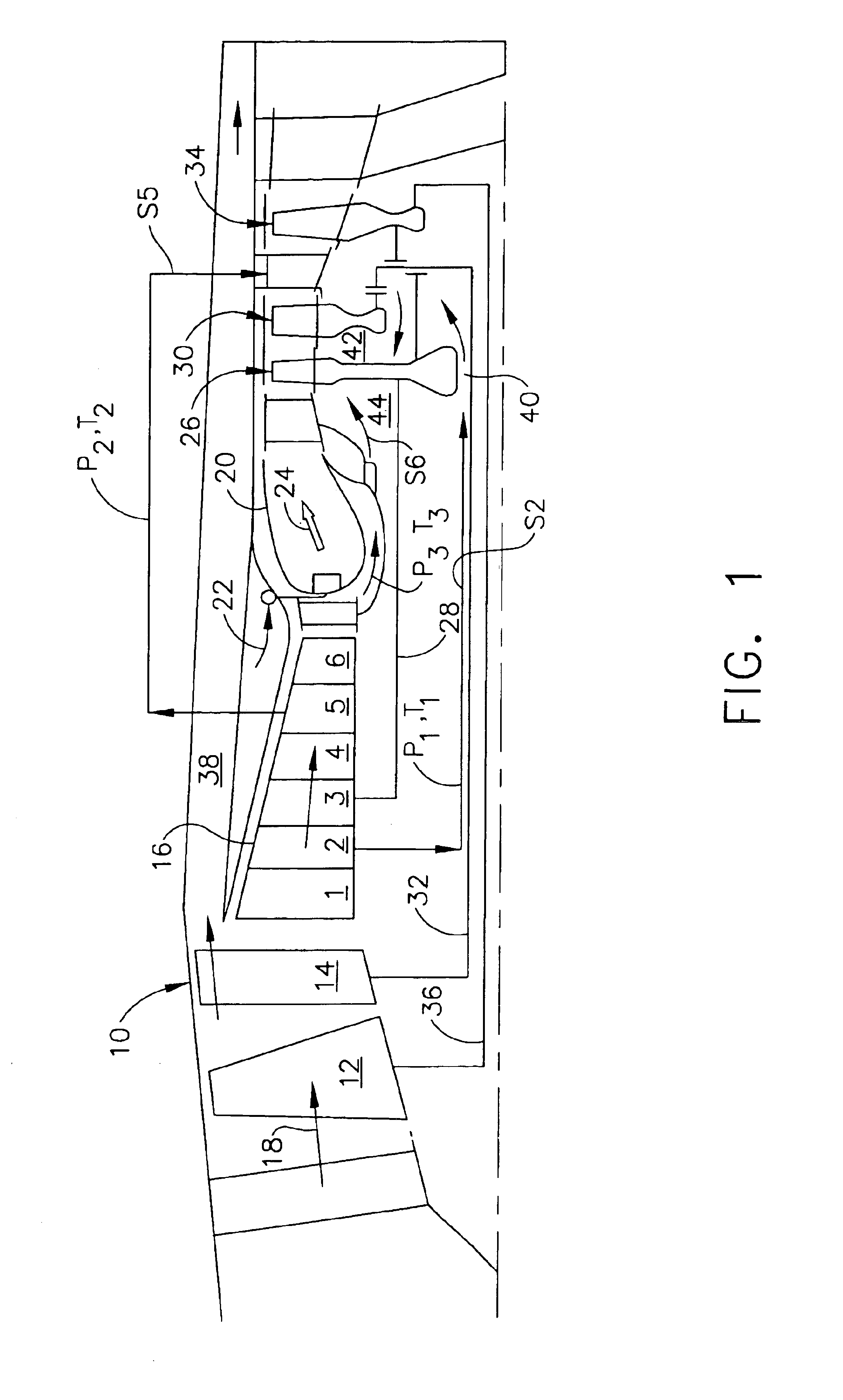
[0017]Illustrated in FIG. 1 is a turbofan gas turbine engine 10 having an exemplary configuration for powering an aircraft in flight. The engine is axisymmetrical about a longitudinal or axial centerline axis and includes a first or forward fan 12, a second or aft fan 14, and a multistage axial compressor 16 joined together in serial flow communication for pressurizing air 18.

[0018]These components may have any conventional configuration, with the first and second fans including corresponding rows of fan blades extending radially outwardly from supporting rotor disks. The axial compressor includes various stages, such as the exemplary six stages 1-6 shown, including corresponding rows of rotor blades extending radially outwardly from corresponding interconnected rotor disks, cooperating with corresponding rows of stator vanes.

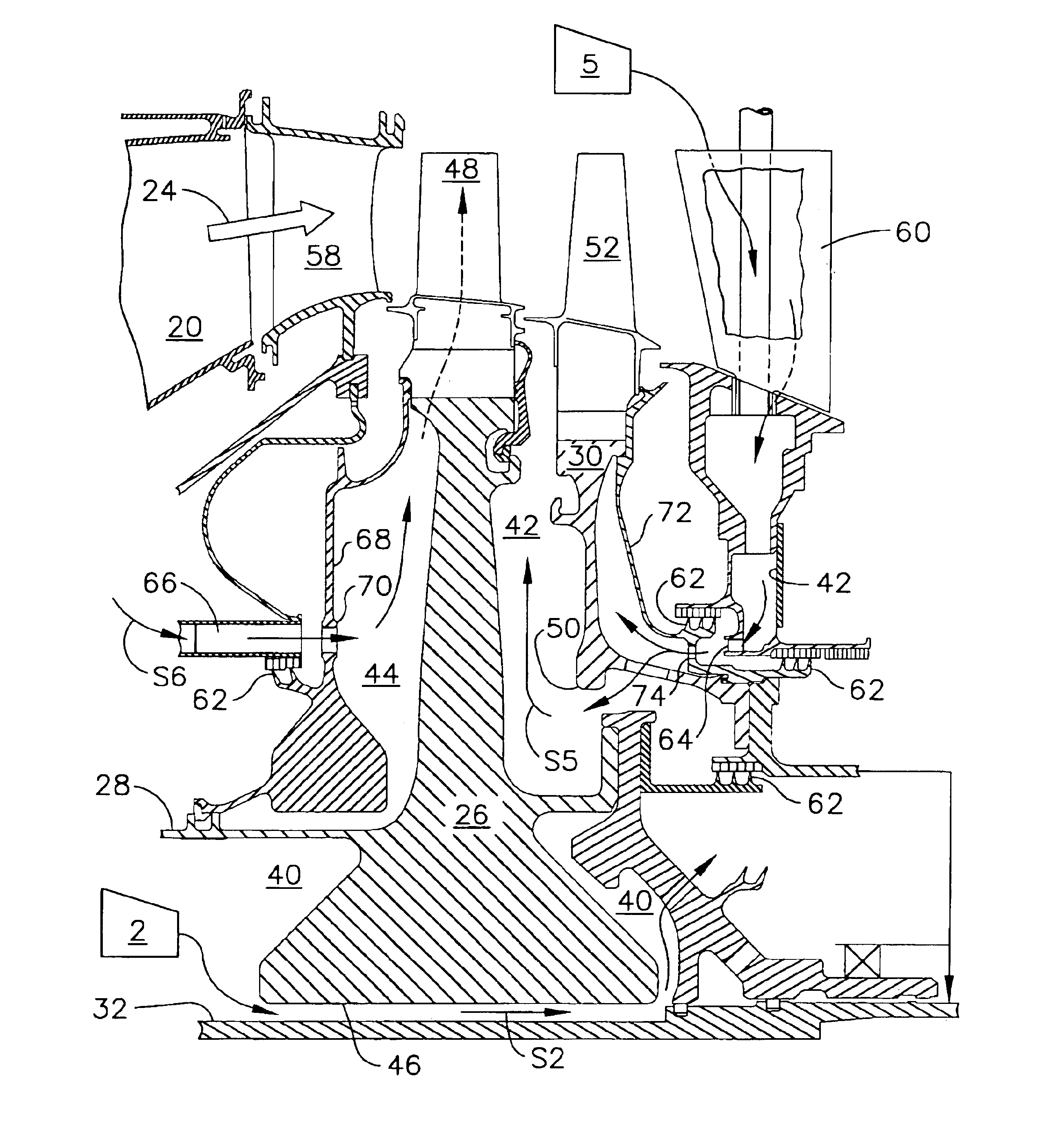
[0019]An annular combustor 20 is disposed at the discharge end of the compressor 16 for mixing fuel 22 with the pressurized air to form hot combustion gases 24...


PUM


Abstract

A turbofan engine includes in serial flow communication a first fan, second fan, multistage compressor, combustor, first turbine, second turbine, and third turbine. The first turbine is joined to the compressor by a first shaft. The second turbine is joined to the second fan by a second shaft. And, the third turbine is joined to the first fan by a third shaft. First, second, and third cooling circuits are joined to different stages of the compressor for cooling the forward and aft sides and center bore of the first turbine with different pressure air.

Description

BACKGROUND OF THE INVENTION[0001]The present invention relates generally to gas turbine engines, and, more specifically, to turbine cooling therein.[0002]In a gas turbine engine air is pressurized in a compressor and mixed with fuel in a combustor for generating hot combustion gases. Multiple turbine stages follow the combustor for extracting energy from the combustion gases to power the compressor and produce useful work.[0003]In a typical turbofan gas turbine engine configuration, a high pressure turbine (HPT) immediately follows the combustor for receiving the hottest combustion gases therefrom from which energy is extracted for powering the compressor. A low pressure turbine (LPT) follows the HPT and extracts additional energy from the combustion gases for powering a fan disposed upstream from the compressor for producing propulsion thrust for powering an aircraft in flight.[0004]The HPT includes a turbine nozzle at the discharge end of the combustor which directs the combustion...

Claims


Application Information

Patent Timeline
Patent Type & Authority Patents(United States)
IPC IPC(8): F03D11/00F01D5/08F01D9/02F01D11/02F01D25/12F02C3/067F02C6/08F02C7/12F02C7/18F02C7/28F02C9/22F16J15/447
CPCF01D5/082F01D5/084F01D5/085F02C7/18F01D25/12Y02T50/676Y02T50/673Y02T50/60
Inventor KRAMMER, ERICH ALOISHAUBERT, RICHARD CLAYLEE, CHING-PANGMACLIN, HARVEY MICHAEL
Owner GENERAL ELECTRIC CO
Why Eureka
Try Eureka