Automated pipetting system

a pipetting system and automatic technology, applied in the field of liquid transfer and dispensing devices, to achieve the effect of greater flexibility and higher throughpu

Inactive Publication Date: 2006-01-03
MATRIX TECH +1
View PDF32 Cites 85 Cited by
  • Summary
  • Abstract
  • Description
  • Claims
  • Application Information

AI Technical Summary

Benefits of technology

[0007]The present invention relates to a multi-channel pipetting system that provides greater flexibility and higher throughput than prior art devices.

Problems solved by technology

However, not all plates have the same well spacings, and not all plates have the same number of wells.

Method used


Image

  • Automated pipetting system
  • Automated pipetting system
  • Automated pipetting system

Examples


Embodiment Construction

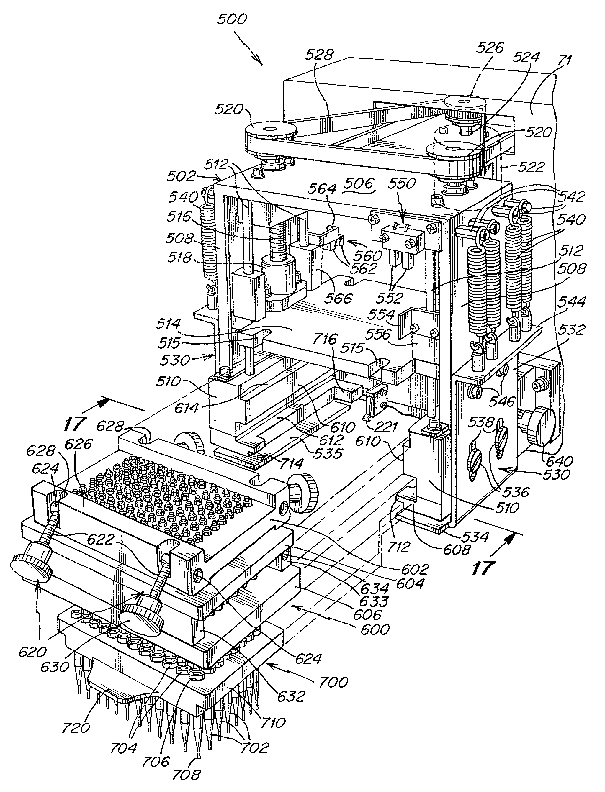
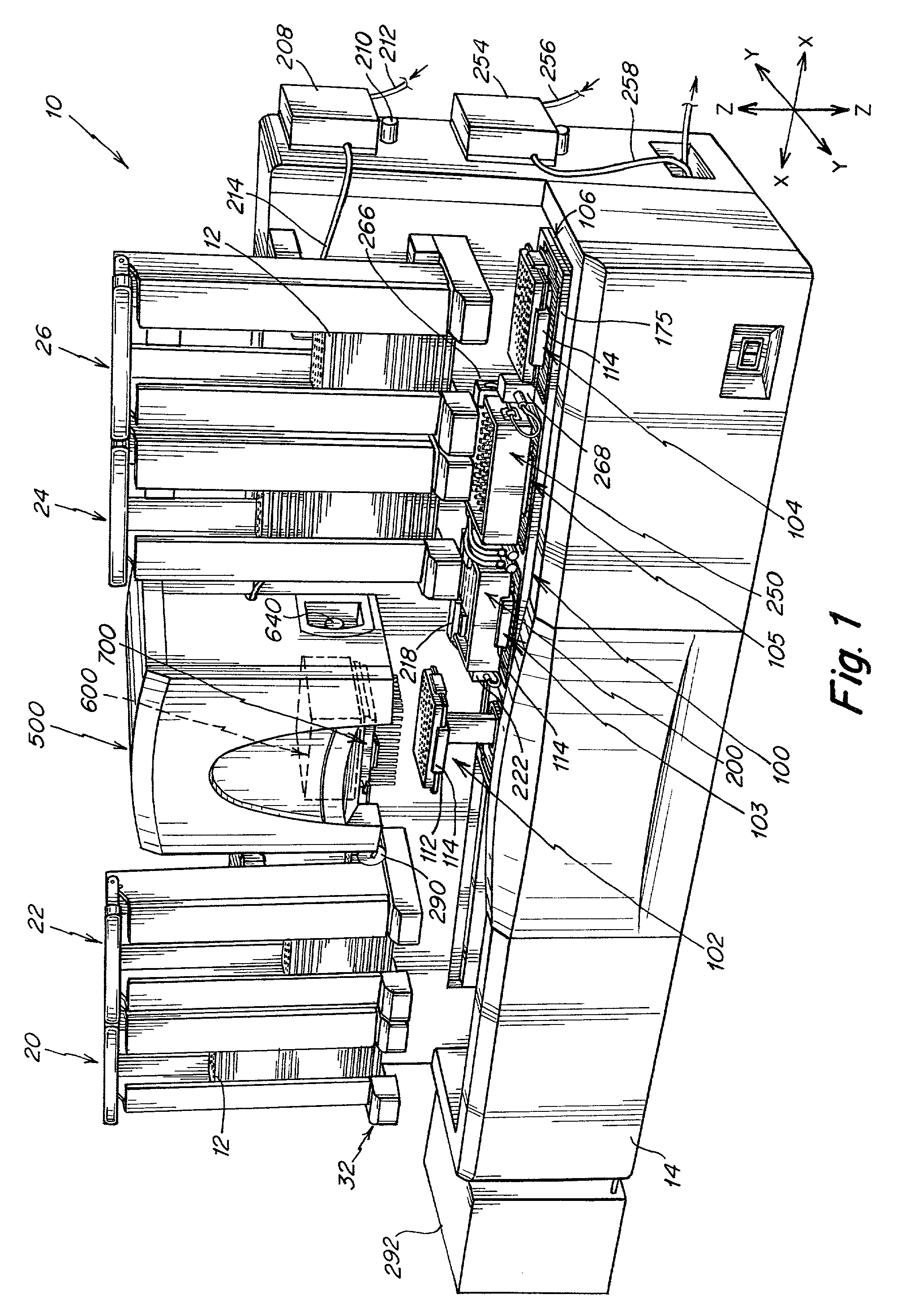
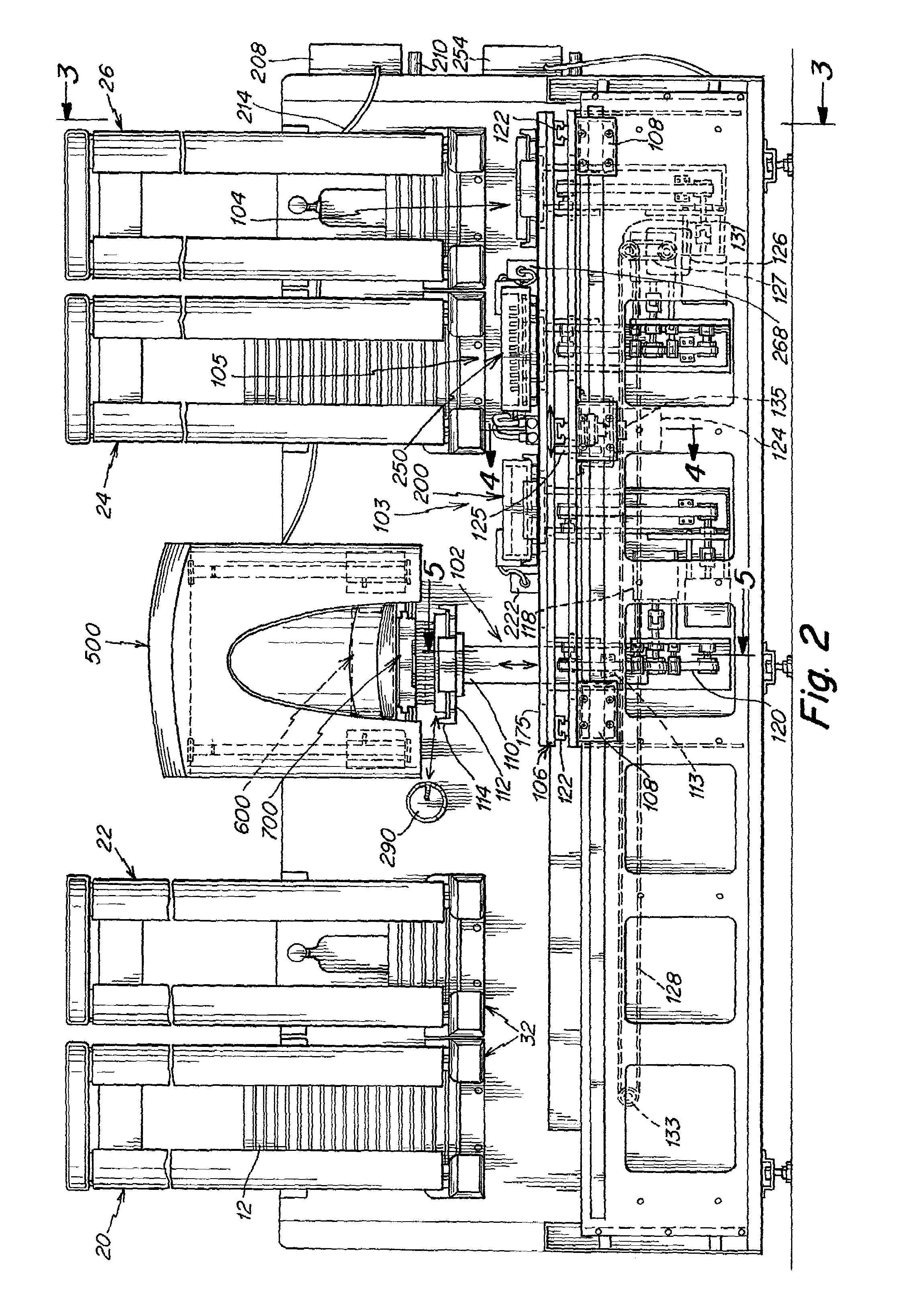
[0058]With reference now to the drawings, and more particularly to FIGS. 1 and 2 thereof, the automated pipetting system 10 of this invention will be described. Pipetting system 10 preferably includes stacker assemblies 20, 22, 24 and 26, pipetting head assembly 500 and plate handling assembly 100. Typically, system 10 includes a plurality of stacker assemblies and a pipetting head assembly 500, that includes at least one head 600, and stacker assemblies typically are disposed on either side of the pipetting head assembly 500. The plate handling assembly 100 transfers plates 12 between the pipetting head assembly 500 and various ones of the stacker assemblies 20–26 as will be described. The pipetting head assembly 500 withdraws liquid from certain “mother” plates 12 or a fill station 200 and transfers it to other “daughter” plates 12, as will be more fully described hereinafter. The operation of all components is controlled by a personal computer or programmable processor 292.

[0059]...


PUM

PropertyMeasurementUnit
liquid dispenseraaaaaaaaaa
flexibleaaaaaaaaaa
clamping forceaaaaaaaaaa

Abstract

A highly automated, high volume multichannel pipetting system which transfers liquid from mother plates to daughter plates, or from a fill station to daughter plates. The mother plates are stacked in one set of stacker assemblies, while the empty daughter plates are stacked in another stacker assembly. A plate handling assembly which is capable of moving the plates in three orthogonal directions retrieves the plates from the stacker assemblies, carries them to the pipetting head, and returns them to other stacker assemblies. The pipetting head is removable for replacement or repair thereof, or for insertion of another head assembly having a different number of pipetting channels. The head slides into the housing on slideways, and is retained in place by manually operable, threaded knobs mounted on shafts. The stacker assemblies include a chimney which is removable from a base. The plates may be stacked in the chimney and then inserted on the base. The base includes solenoids whose arms are retractable to permit plates to be retrieved or replaced one at a time. The chimneys contain flaps which serve to retain the plates within the chimney if manually removed from the base. Doors in the stacker chimneys allow manual insertion and replacement of plates. Methods of operation of the pipetting system are also disclosed.

Description

FIELD OF THE INVENTION[0001]This invention relates generally to liquid transfer and dispensing devices for liquid reagents and samples, and more particularly to a highly automated, high throughput multichannel pipetting system.BACKGROUND OF THE INVENTION[0002]Pipetting systems are well known, and typically are used in laboratories and hospitals for the aspiration and dispensing of relatively small, predetermined quantities of liquids into the wells of plates such as microplates or deep well blocks or the like. Examples of the liquids being dispensed include blood, other biological samples, solvents, reagents and the like. Liquid is normally drawn by suction from one set of plates or the like and subsequently released into the wells of other plates or the like. Typically, pipette tips are used to draw some or all of the fluid from one set of wells in a plate or reservoir and transfer it to another set of wells in another plate.[0003]For high volume, automated systems, the spacing of ...

Claims


Application Information

Patent Timeline
Patent Type & Authority Patents(United States)
IPC IPC(8): B01L3/02G01N1/10G01N21/00G01N35/02G01N35/04G01N35/10
CPCG01N35/028G01N35/04G01N35/1002G01N35/1067G01N35/1074Y10T436/113332G01N2035/1069Y10T436/114165Y10T436/119163Y10T436/11Y10T436/2575G01N2035/0425
Inventor HAMEL, MARC F.MATHUS, GREGCOTE, RICHARDMAEDA, YOSHIOOHTOMO, CHIKASHI
Owner MATRIX TECH
Why Eureka
Try Eureka