Hybrid electric linear actuator

a technology of electric linear actuators and actuators, applied in the direction of mechanical actuators, generators/motors, transportation and packaging, etc., can solve the problems of controllability problems and other problems

Inactive Publication Date: 2006-01-03
TOYOTA JIDOSHA KK +1
View PDF6 Cites 66 Cited by
  • Summary
  • Abstract
  • Description
  • Claims
  • Application Information

AI Technical Summary

Benefits of technology

[0004]Pursuant to the present invention, a hybrid actuator capable of imparting a linear drive force to a load is provided with both solid-state thrusters and electric linear motors through which such drive force is generated and applied in opposite directions to the load through sets of clutch units under control of compliant stroke and force amplification devices. The arrangement and

Problems solved by technology

Because hydraulic cylinder type linear actuators heretofore utilized have a low power density, attempts have been made to replace such hydraulic actuators with electromechanical types of linear actuators with higher power density without success because of reliability a

Method used


Image

  • Hybrid electric linear actuator
  • Hybrid electric linear actuator
  • Hybrid electric linear actuator

Examples


Embodiment Construction

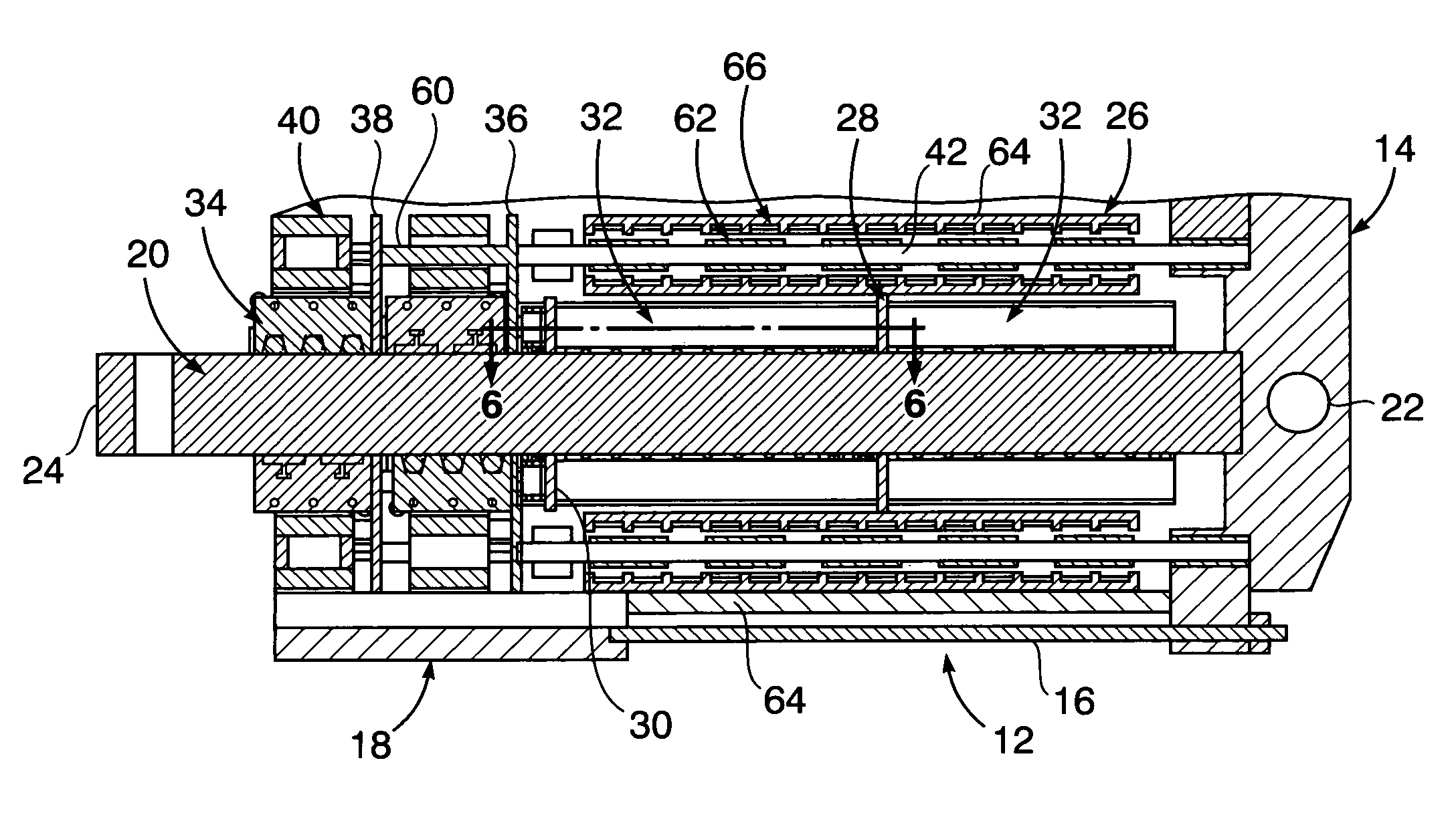
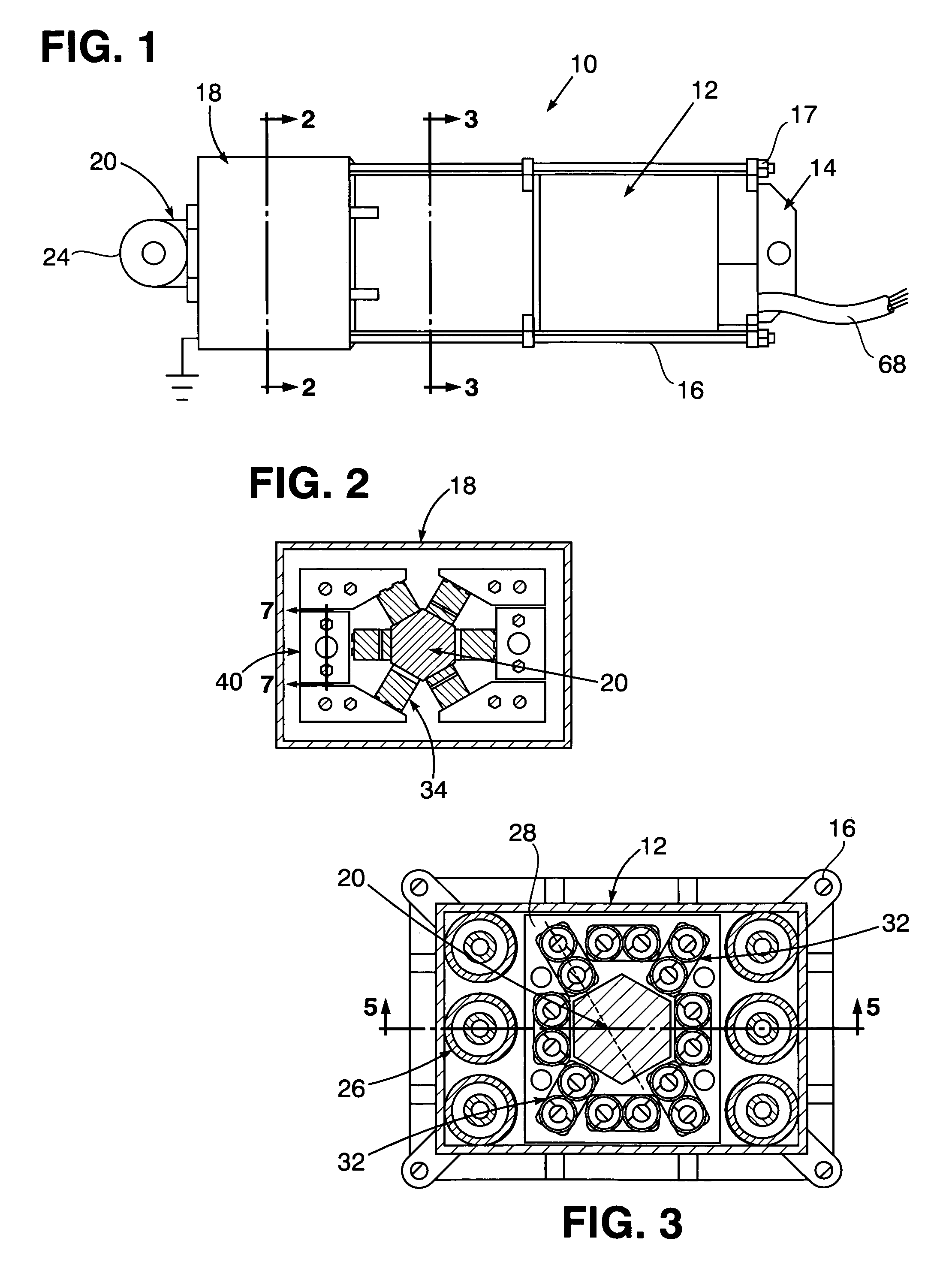
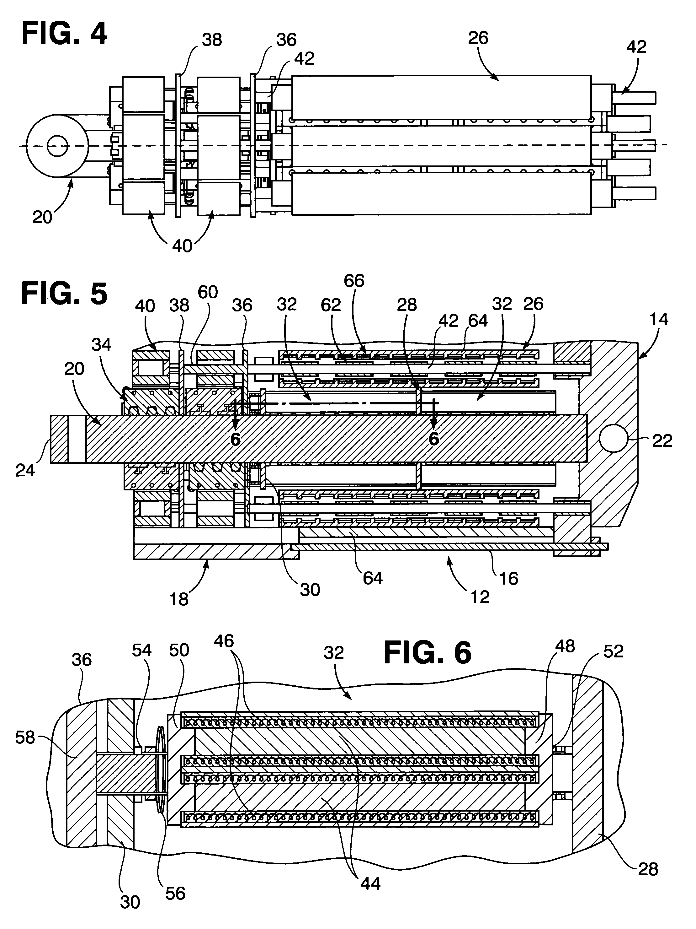
[0012]Referring now to the drawing in detail, FIG. 1 illustrates a hybrid actuator 10 having an axially elongated housing section 12 adapted to be fixedly anchored at one axial end by a mounting piece 14. A pair of elongated, parallel-spaced bolts 16 with nuts 17 on the ends thereof interconnect the housing section 12 with a somewhat larger housing section 18 at the other axial end of the hybrid actuator 10 from which an actuating shaft 20 projects for attachment to a load to be driven.

[0013]As shown in FIGS. 2 and 3, the shaft 20 is of a dimensionally constant, six-sided cross-sectional shape extending throughout the actuator 10 between axial shaft end 22 and axial shaft end 24 at which the shaft 20 is attachable to the load for imparting a drive force thereon. Positioned within the actuator housing section 12, which is of rectangular cross-sectional shape as shown in FIG. 3, are six tubular motors 26 of a linear synchronous permanent magnet type. Such motors 26 are disposed in rad...


PUM


Abstract

A hybrid linear actuator features a central load shaft on which a plurality of solid-state magnetostrictive thrusters are positioned in operative relation to electric motors of a permanent magnet synchronous type to impart linear thrust force to the load shaft through clutch units also positioned thereon and under control of force and stroke amplification of output force from motor shafts projecting from the motors.

Description

[0001]The present invention relates to a high thrust force producing actuator.BACKGROUND OF THE INVENTION[0002]High powered, long stroke linear actuators as generally known in the art involve use of solid-state thrusters, motors, self-activating clutches and compliant gearing. Such actuators are disclosed for example in U.S. Pat. Nos. 5,705,863 and 6,294,849, featuring methods of enhancing operation of a magnetostrictive type of motor to minimize and limit stroke impact.[0003]Because hydraulic cylinder type linear actuators heretofore utilized have a low power density, attempts have been made to replace such hydraulic actuators with electromechanical types of linear actuators with higher power density without success because of reliability and scaling problems with power screws. Controllability problems have also occurred with respect to the clutch units associated with linear actuators, while stroke limiting problems were heretofore associated with the use of solid-state thrusters ...

Claims


Application Information

Patent Timeline
IPC IPC(8): H02N2/00H02K41/03
CPCH01L41/12H02K7/06H02N2/021H02K7/116H02K16/00H02K7/106H10N35/00
Inventor SENDAULA, MUSOKE H.TETER, JOSEPH P.BRADY, DAVID J.
Owner TOYOTA JIDOSHA KK
Why Eureka
Try Eureka