
Hybrid reactive power compensation device

Active Publication Date: 2006-01-03
ABLEREX ELECTRONICS CO LTD
View PDF9 Cites 15 Cited by
  • Summary
  • Abstract
  • Description
  • Claims
  • Application Information

AI Technical Summary

Benefits of technology

[0013]The primary objective of this invention is to provide a hybrid reactive power compensation device including a passive type reactive power compensator and an active type reactive power compensator serially connected thereto, which is adapted to supply a linearly adjustable reactive power and thereby avoid the destruction of power resonance. The manufacture cost of this invention is less expensive than that of the conventional active type reactive power compensator.
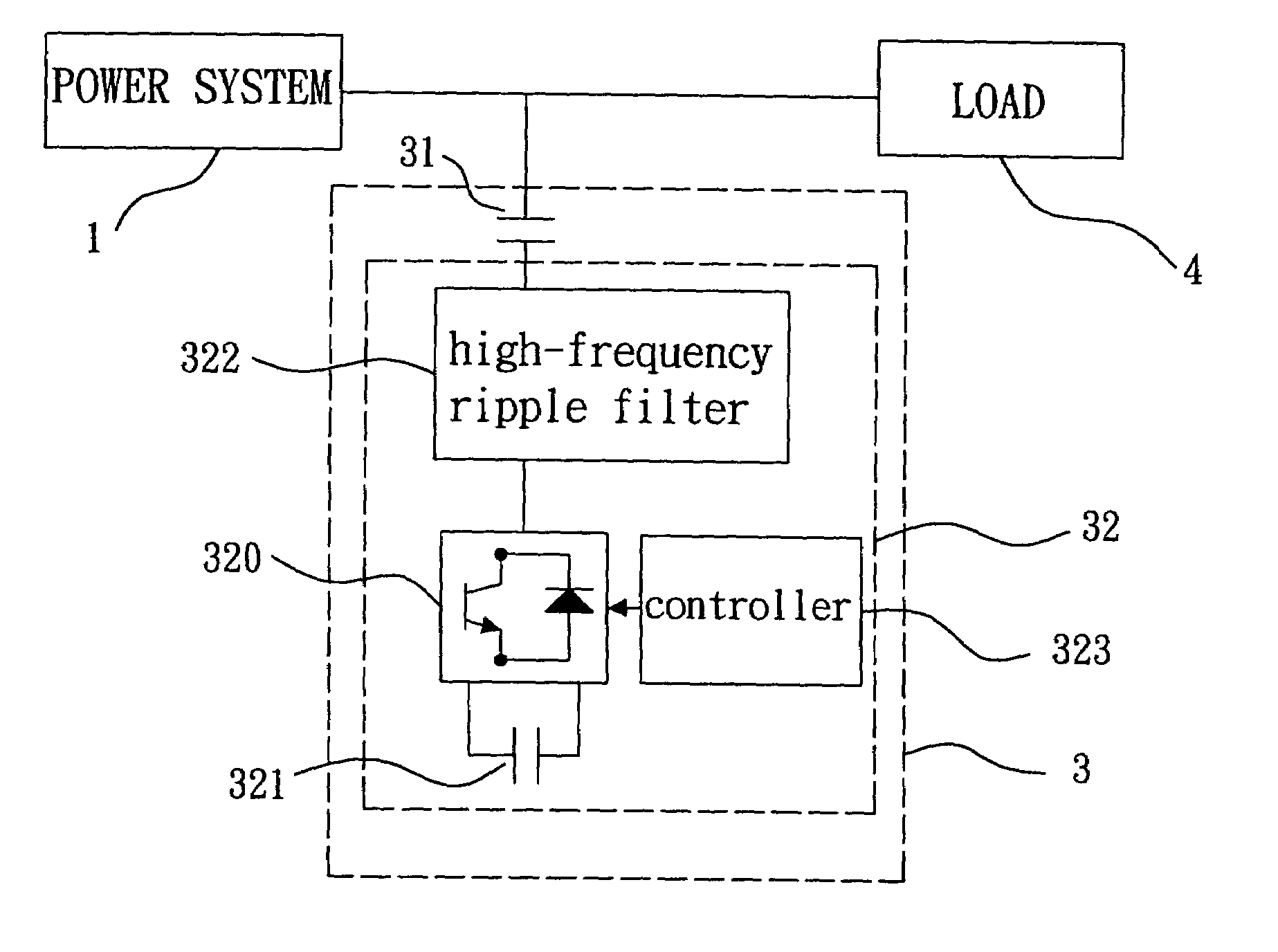
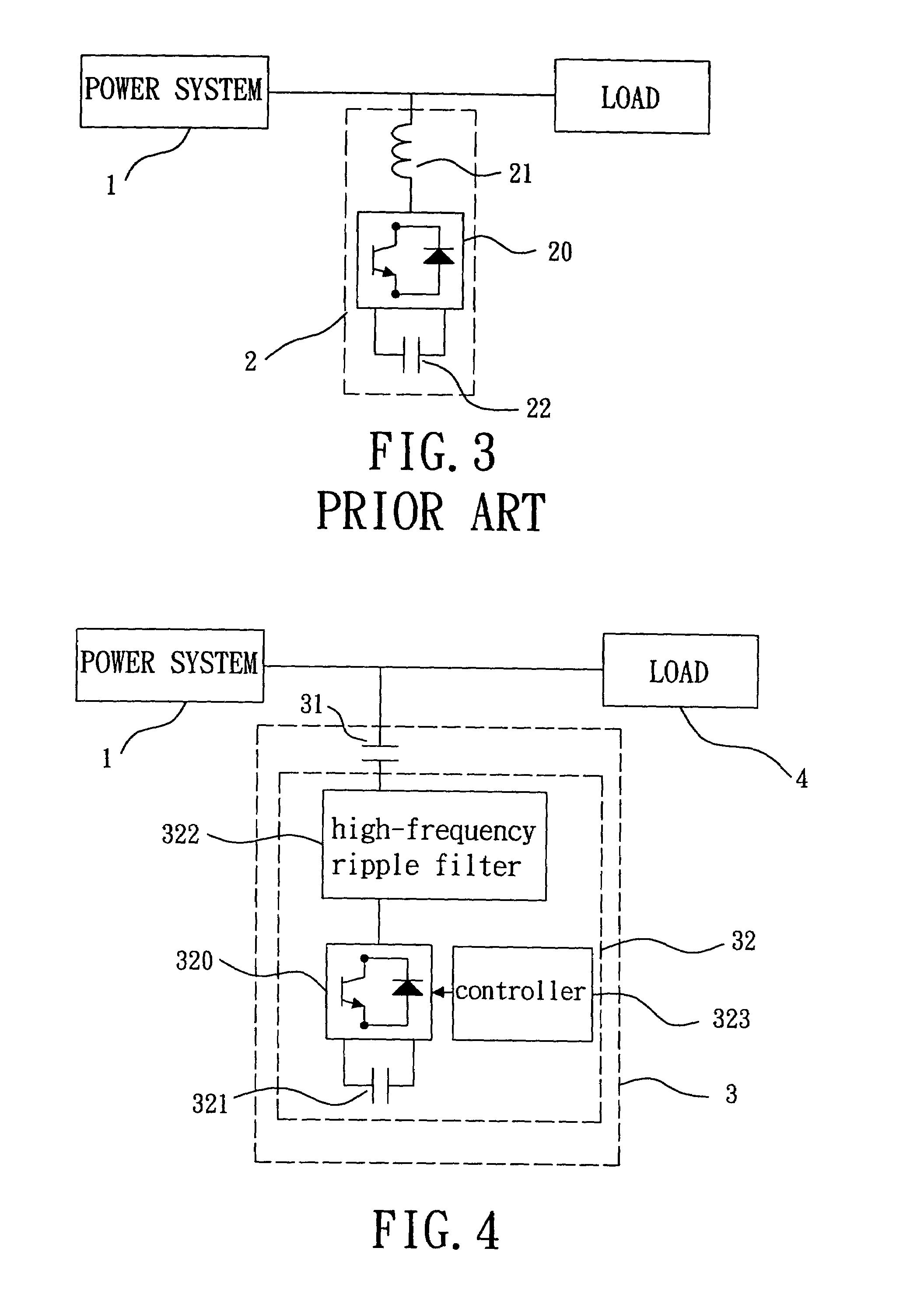
[0014]The hybrid reactive power compensation device in accordance with the present invention mainly comprises a passive type reactive power compensator and an active type reactive power compensator serially connected thereto. The passive type reactive power compensator is an AC power capacitor adapted to provide reactive power that, thus, reduces reactive power supplied from the active type reactive power compensator. Additionally, it can reduce the voltage rating and the capacity of active type reactive power compensator. Since the cost of AC power capacitor is less expensive significantly than that of the active type reactive power compensator, the manufacture cost of the present invention is also less expensive than that of the conventional active type reactive power compensator. The active type reactive power compensator comprises a power converter, a DC capacitor, a high-frequency ripple filter and a controller. The hybrid reactive power compensation device is adapted to supply linearly adjustable reactive power within a predetermined range. The hybrid reactive power compensation device can supply a current with a nearly sinusoidal waveform for reactive power compensation due to the use of active type reactive power compensator, and thereby it can avoid the power resonance generated by itself and reactance of the power system. Therefore, it can avoid the destruction of the hybrid reactive power compensator device itself and neighboring power facilities due to power resonance.

Problems solved by technology

Additionally, it can reduce the voltage rating and the capacity of active type reactive power compensator.

Method used


Image

  • Hybrid reactive power compensation device
  • Hybrid reactive power compensation device
  • Hybrid reactive power compensation device

Examples


Embodiment Construction

[0024]FIG. 4 illustrates a system structure of a hybrid reactive power compensation device in accordance with the first embodiment of the present invention. Referring to FIG. 4, the hybrid reactive power compensation device 3 is parallel connected between a power system 1 and a load 4. The power system 1 provides an AC power to the load 4. The hybrid reactive power compensation device 3 is adapted to compensate the reactive power required by the load 4 to thereby improve the power factor from the view of power system 1. The hybrid reactive power compensation device 3 includes a passive type reactive power compensator 31 and an active type reactive power compensator 32 serially connected thereto. The passive type reactive power compensator 31 is a power capacitor adapted to supply the reactive power, thereby reducing the reactive power supplied from the active type reactive power compensator 32. The active type reactive power compensator 32 includes a power converter 320, a DC power ...


PUM


Abstract

A hybrid reactive power compensation device comprises a passive type reactive power compensator and an active type reactive power compensator serially connected thereto. The passive type reactive power compensator is an AC power capacitor adapted to provide the reactive power that reduces capacity of the active type reactive power compensator. The active type reactive power compensator comprises a power converter, a DC capacitor, a high-frequency ripple filter and a controller. The hybrid reactive power compensation device can supply a linearly adjustable reactive power within a predetermined range, and is adapted to supply a current with a nearly sinusoidal waveform. Therefore, it can avoid the destruction of AC power capacitor caused by the power resonance.

Description

BACKGROUND OF THE INVENTION[0001]1. Field of the Invention[0002]The present invention is related to a hybrid reactive power compensation device including a passive type reactive power compensator and an active type reactive power compensator serially connected thereto, which are adapted to supply a linearly adjustable reactive power within a predetermined range in the distribution power system. Moreover, the present invention is related to a hybrid reactive power compensation device including an active type reactive power compensator adapted to adjust a current flowing through the passive type reactive power compensator to be approximated as a sinusoidal waveform, and thereby it can avoid the power resonance generated between the passive type reactive power compensator and the reactance of power system that may cause destruction of the reactive power compensation device itself and adjacent power facilities.[0003]2. Description of the Related Art[0004]Most loads in a distribution pow...

Claims


Application Information

Patent Timeline
IPC IPC(8): G05F1/70H02J3/18
CPCG05F1/70
Inventor WU, CHIN-CHANGCHOU, HURNG-LIANGHSU, WEN-PINCHANG, YAO-JEN
Owner ABLEREX ELECTRONICS CO LTD
Learn More