Pivot hinge with positioning function

a technology of positioning function and pivoting hinge, which is applied in the direction of wing accessories, instruments, and details of portable computers, can solve the problems of pivoting hinges eventually breaking down, and achieve the effect of improving positioning effect and reducing shaft abrasion

Inactive Publication Date: 2006-01-10
SHIN ZU SHING
View PDF14 Cites 67 Cited by
  • Summary
  • Abstract
  • Description
  • Claims
  • Application Information

AI Technical Summary

Benefits of technology

[0008]The second object of the invention is to provide a pivot hinge that can significantly reduce abrasion of the shaft against the pivot tube otherwise occurring due to constant turning of the pivot hinge. According to the present design, the pivot tube located on the base plate and the middle section of the shaft, each having a plain facet, will be closely mated only when the two plain facets are matched up in the rotation of the shaft around the tube wall of the pivot tube, that is when the pivot hinge is turned to the locking position.
[0017]The use of the interlocking tooth and notch enables the movable display panel to be placed in the horizontal direction over the main unit, but leaving a predetermined gap between the movable display panel and the main unit, so as to keep the movable display panel from hitting the main unit when the movable display panel is folded down. Each having a plain facet on the surface, the middle section of the shaft and the pivot tube will be closely mated only when the two plain facets are matched up in the rotation of the shaft, thus this can reduce abrasion of the shaft against the pivot tube otherwise occurring due to constant turning and improve the positioning effect.

Problems solved by technology

However, since the conventional pivot is a circular rod, constant turning of the pivot hinge produces abrasion on the shaft and the base plate over a period of time, so the pivot hinge will eventually break down.

Method used


Image

  • Pivot hinge with positioning function
  • Pivot hinge with positioning function
  • Pivot hinge with positioning function

Examples


Embodiment Construction

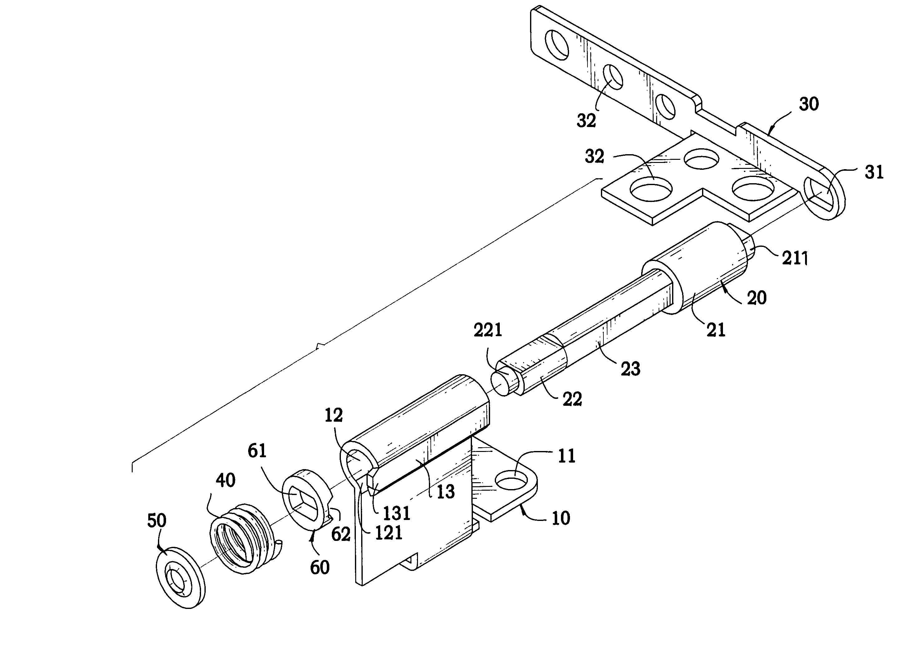
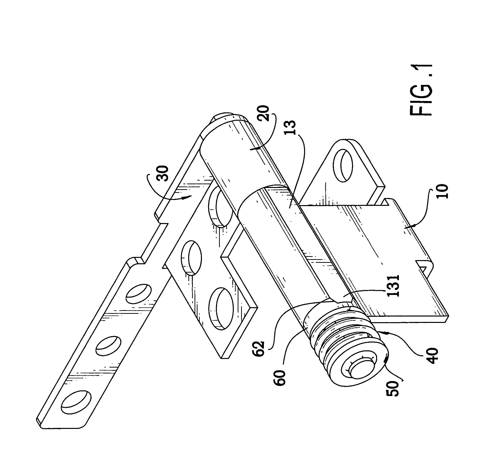
[0023]The present invention is illustrated through a preferred embodiment as shown in FIG. 1, in which a pivot hinge, used to couple the movable display panel to the main unit of the portable electronic device, comprises a base plate (10), a shaft (20), a locating bracket (30), a spring (40), a ring (50) and a locking piece (60).

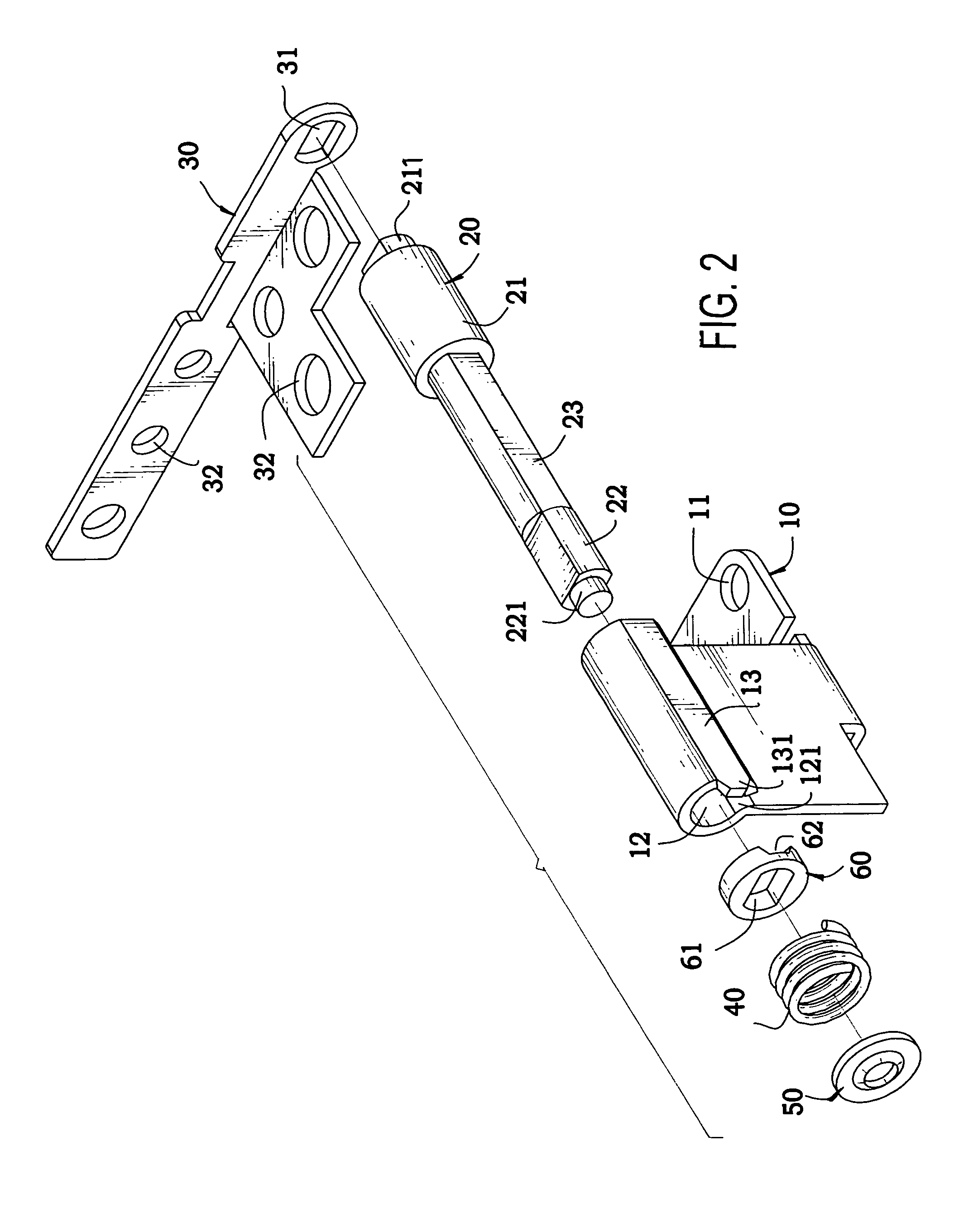
[0024]The base plate (10), as shown in FIG. 2, is an L-shaped metal plate, with several locating holes (11) on one end and a pivot tube (12) on the other end. The pivot tube (12) has a gap (121) on the tube wall to form a semi-closed cylinder that allows the head end of the shaft (20) to pass through during assembling of the spring. The pivot tube (12) also has a plain facet (13) on the surface, and a cone-shaped tooth (131) that extends from one end of the pivot tube (12) and is in line with the plain facet (13).

[0025]The locking piece (60) has an oval hole (61) in the center, and a notch (62) on the perimeter of the flange corresponding to the position of ...


PUM


Abstract

A pivot hinge for a portable electronic device is disclosed. A base plate with a pivot tube is fixed on the main unit of the portable electronic device, and a locating bracket is fixed on the movable display panel. A shaft is inserted through the pivot tube, exposing the angular section from the other end of the pivot tube. A locking piece, a spring, and a ring are sequentially inserted over the angular section to complete the spring assembly. The interlocking of the tooth and notch enables the movable display panel to be placed in the horizontal direction over the main unit. A middle section of the shaft and the pivot tube are closely mated only when two plain facets respectively formed on the shaft and the pivot tube are matched up in the rotation of the shaft, thus abrasion damage is significantly reduced.

Description

BACKGROUND OF THE INVENTION[0001]1. Field of the Invention[0002]The present invention is related to a pivot hinge for portable electronic devices, and more particularly to a pivot hinge with positioning function.[0003]2. Description of Related Art[0004]Nowadays portable electronic devices such as notebook computers, personal translators, personal digital assistants (PDA) are well received by consumers. Notebook computers usually have a liquid crystal display (LCD) housed in a movable display panel, and a keyboard and a processing unit installed in a main unit. The movable display panel is coupled to the main unit by means of a pivotal mechanism, such that the user only has to flip up the movable display panel along the pivot in order to operate the notebook computer, and to flip down the movable display panel in order to close the notebook computer.[0005]Basically, a conventional pivot hinge includes a shaft, a locking piece, and a base plate, where the locking piece has a notch tha...

Claims


Application Information

Patent Timeline
Patent Type & Authority Patents(United States)
IPC IPC(8): E05C17/64E05D11/10E05D11/08G06F1/16
CPCG06F1/1616G06F1/1681G06F1/1679E05D11/084E05Y2900/606Y10T16/540255Y10T16/5387Y10T16/54038
Inventor LU, SHENG-NANLEE, CHUNG-YU
Owner SHIN ZU SHING
Why Eureka
Try Eureka