
Cold formed latch wire

a technology of latch wires and latch wires, which is applied in the field of latch wires and anchorage systems, can solve the problems of reducing the rigidity on which is relied on the position and alignment the inability to secure the child seat, and the welding distorts the position of the latch wires, so as to achieve greater strength and rigidity.

Inactive Publication Date: 2006-01-10
MAGNA CLOSURES INC
View PDF41 Cites 15 Cited by
  • Summary
  • Abstract
  • Description
  • Claims
  • Application Information

AI Technical Summary

Benefits of technology

The present invention provides an improved restraint anchorage for a child safety seat in a vehicle. The apparatus uses a cross member, mounting brackets, and latch wires to secure the seat in place. The latch wires are strengthened to resist bending loads, while maintaining the industry standard diameter at the retention zone. The latch wires have tapered legs that provide greater strength and rigidity under bending loads. The method for manufacturing the restraint anchorage includes shaping the latch wire legs to provide greater strength and resist bending loads, while reinforcing the latch wire with minimal additional components and cost. The technical effects of the invention include increased safety for children, improved stability of the child safety seat, and reduced risk of injury during accidents.

Problems solved by technology

The child safety seat mounting procedure is awkward and sometimes complex, which may result in improper securement of the child safety seat to the seat of the vehicle.
However, welding distorts position and alignment of the latch wires.
The enlarged openings reduce rigidity relied upon for support, positioning and alignment, and make the assembly more susceptible to deformation due to welding heat.
However, this arrangement does not resist deformation of the latch wire caused by use or abuse of the child safety seat as much as may be necessary.
However, latch wires having such a constant diameter have difficulty meeting the requirements for maximum allowable deflection.
However, this method is problematic in that it adds an additional component increasing both the cost and assembly required.

Method used


Image

  • Cold formed latch wire
  • Cold formed latch wire
  • Cold formed latch wire

Examples


Embodiment Construction

)

[0026]As required, detailed embodiments of the present invention are disclosed herein. However, it is to be understood that the disclosed embodiments are merely exemplary of an invention that may be embodied in various and alternative forms. Therefore, specific functional details disclosed herein are not to be interpreted as limiting, but merely as a representative basis for the claims and / or as a representative basis for teaching one skilled in the art to variously employ the present invention.

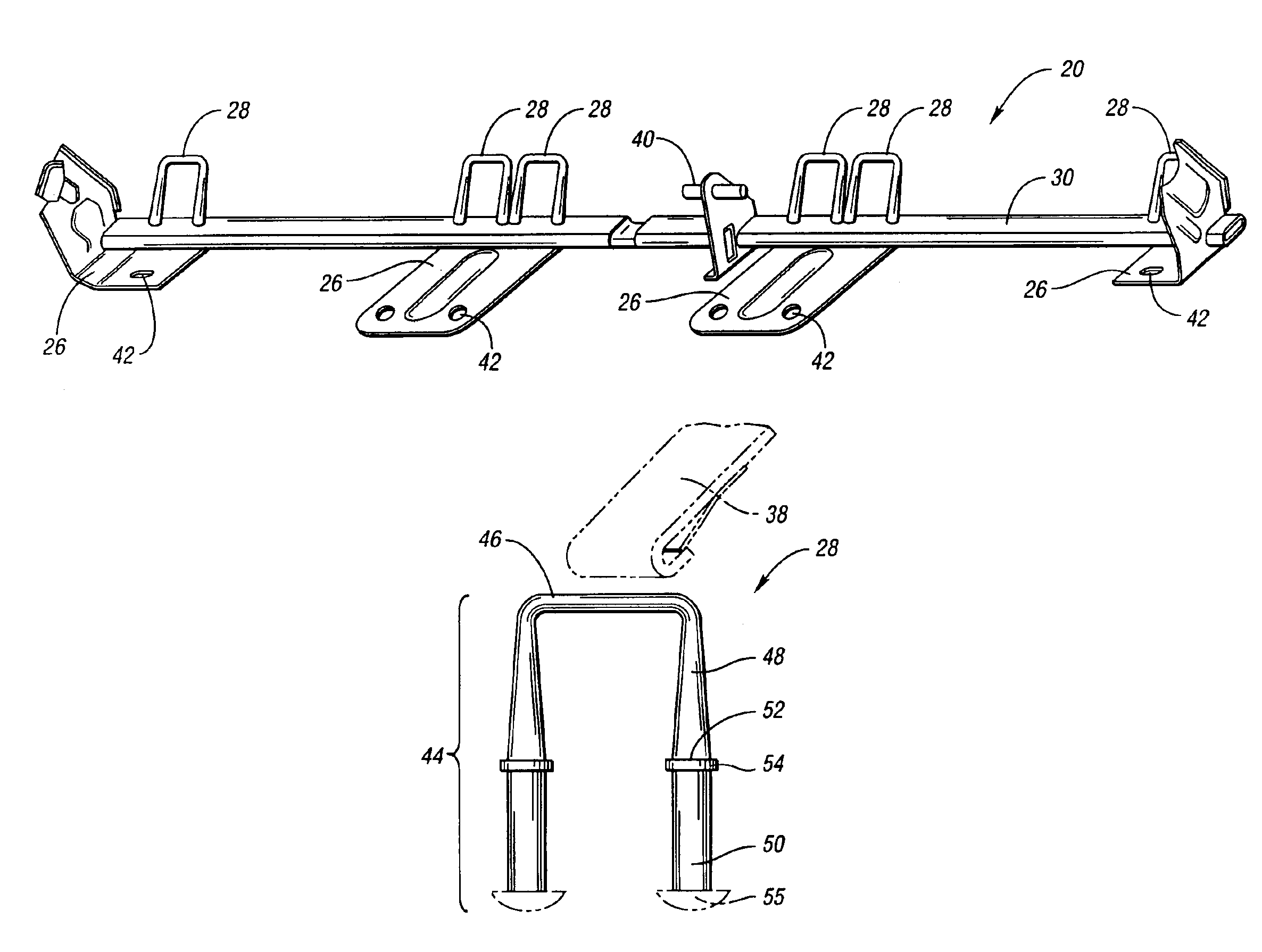
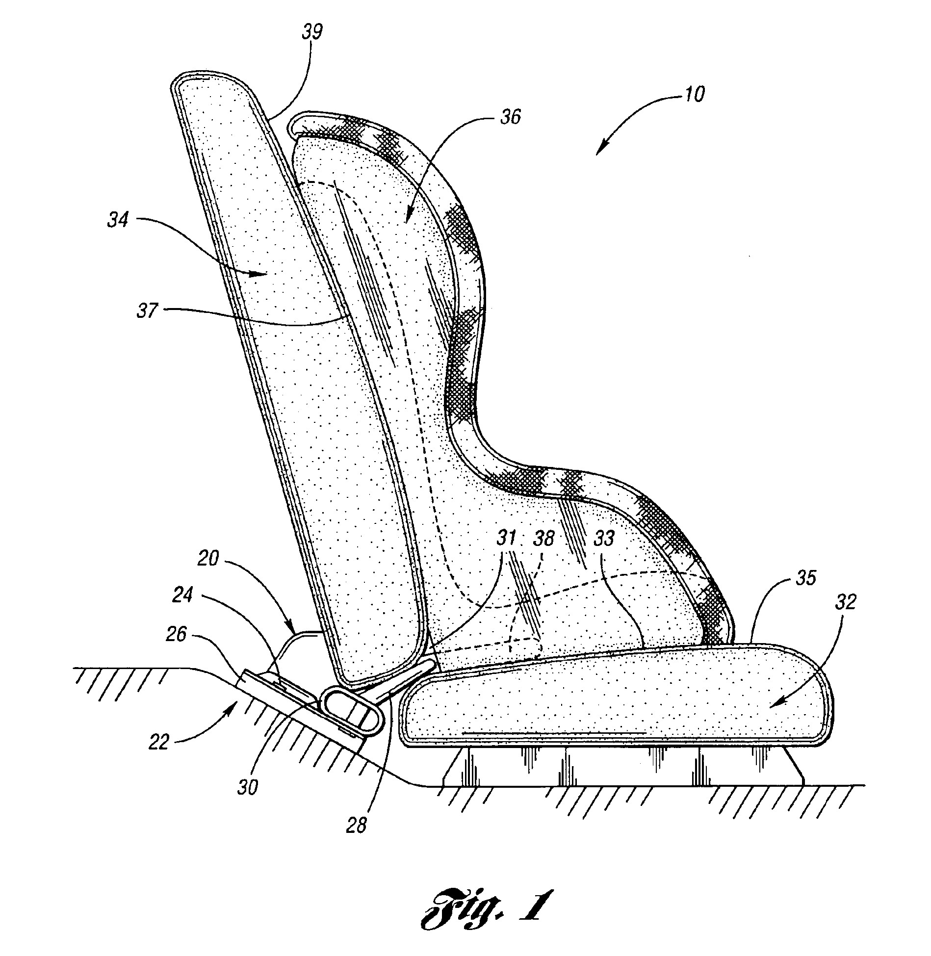
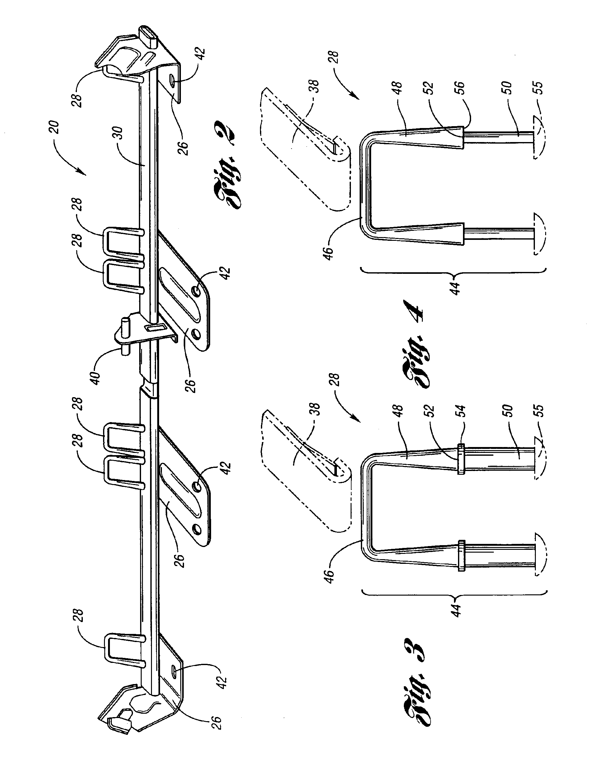
[0027]Referring now to the Figures, an environmental view of the latch wire and restraint anchorage system of the present invention is illustrated in FIGS. 1 and 2. An anchorage 20 is fastened to the floor 22 of a vehicle 10 with bolts 24, which extend through anchorage brackets 26. The anchorage 20 includes a plurality of latch wires 28 attached to a cross member 30. The anchorage 20 and latch wires 28 are positioned such that the latch wires 28 extend through a channel 31 formed between a ...


PUM


Abstract

A latch restraint and safety anchorage system for securing a child safety seat in an automotive vehicle behind the vehicle's seat is provided. One or more latch wires are generally mounted to a cross member of the anchorage system comprised of a pair of spatially separated legs joined at one end by a transverse latch bar. Each leg includes a tapered portion and an end portion. The end portion is exposed to allow the legs to be retained by the cross member.

Description

BACKGROUND OF THE INVENTION[0001]1. Field of the Invention[0002]The invention relates to child seat restraints for automotive vehicles and, in particular, to a latch restraint and anchorage system for securing the child restraint seat to the seat of a vehicle.[0003]2. Background Art[0004]Child safety seats have been required for many years by law for small children riding in automotive vehicles. In the past, child safety seats have been secured to a passenger seat using standard seatbelts provided for adult passengers that are anchored to one or more structural members of the vehicle. The seatbelts are normally threaded through apertures or slots provided in the child safety seat secure the child safety seat in position on the vehicle seat. The child safety seat mounting procedure is awkward and sometimes complex, which may result in improper securement of the child safety seat to the seat of the vehicle.[0005]To overcome these problems, various regulations have been implemented req...

Claims


Application Information

Patent Timeline
Patent Type & Authority Patents(United States)
IPC IPC(8): B23P11/00B60N2/28
CPCB60N2/286B60N2/289Y10T29/4992Y10T24/4773Y10T29/49915Y10T29/49622Y10T29/49924B60N2/26B60N2/28
Inventor DUFFY, MICHAEL J.AUSTIN, DONALD M.SMALLWOOD, DAVID J.
Owner MAGNA CLOSURES INC
Learn More