Gas distribution device

a gas distribution device and gas distribution technology, applied in the direction of positive displacement liquid engines, lighting and heating apparatus, liquid fuel engines, etc., can solve the problems of pressure loss generation, complex and expensive oil distribution systems in this case, and prohibitively expensive systems in air-conditioning applications. achieve the effect of simple equalization lines

Active Publication Date: 2006-01-10
DANFOSS COMML COMPRESSORS +1
View PDF15 Cites 16 Cited by
  • Summary
  • Abstract
  • Description
  • Claims
  • Application Information

AI Technical Summary

Benefits of technology

[0017]The present invention overcomes the disadvantages of the previous devices exhibiting overcomplexity or pressure losses in the oil suction or equalization lines by using a particular geometry to equalize the pressures in the oil pans of each compressor and thus use simple equalization lines.
[0027]The present invention according to one exemplary embodiment is also characterized in that the distance between two branches of the distribution tube is at least five times the outside diameter of the distribution tube. The distance between the branches prevents perturbations in the velocity profile brought about by one branch from altering the gas behavior in the next branch.
[0031]The present invention according to one exemplary embodiment is also characterized in that the straight portion of the last branch tube positioned in the axis of the distribution tube and communicating therewith has a length equal to at least five times the outside diameter of the distribution tube. This straight portion prevents perturbations in the velocity profile brought about by the penultimate branch from altering the gas behavior in the last branch.
[0032]The present invention according to one exemplary embodiment is also characterized in that at least one of the branch tubes has a collar at its end joined to the distribution tube. The collar attachment prevents welds from projecting into the flow, causing pressure losses and reducing the reliability of the device.

Problems solved by technology

Oil apportioning systems in this case are complex and expensive, based on combining common oil collectors, devices for measuring individual levels, and solenoid distribution valves.
These systems are prohibitively expensive in air-conditioning applications.
The disadvantage of this system resides in the pressure losses generated, which have a direct impact on the energy performance of the cooling system.
Moreover, producing several welds to create local pressure losses impacts cost as well as reliability, as the welds increase the risk of leakage.
These two solutions result in an unequal supply of gas and oil to the compressors, with the desired pressure difference equalizing the oil levels through a simple pipe.

Method used


Image

  • Gas distribution device
  • Gas distribution device
  • Gas distribution device

Examples


Embodiment Construction

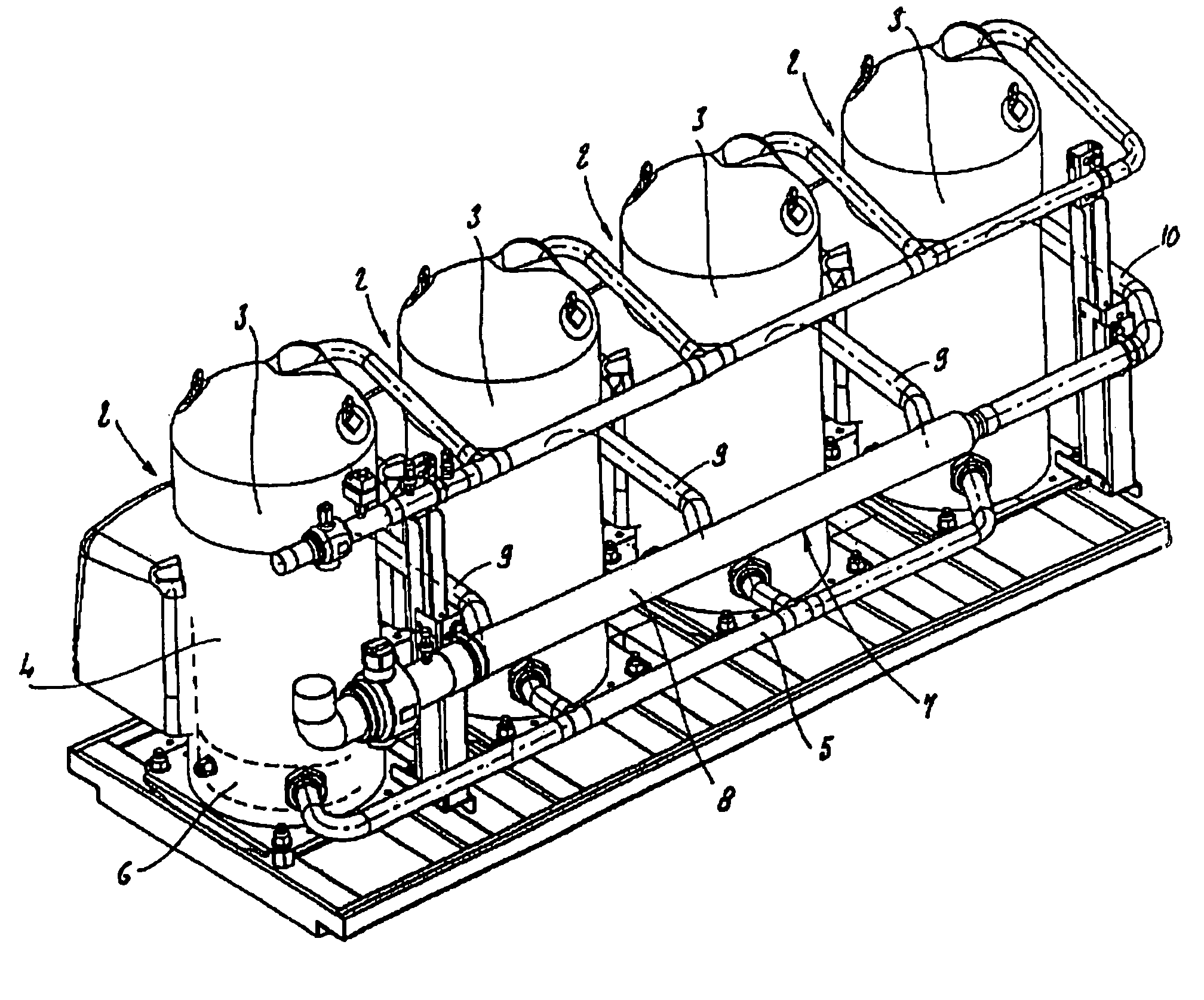
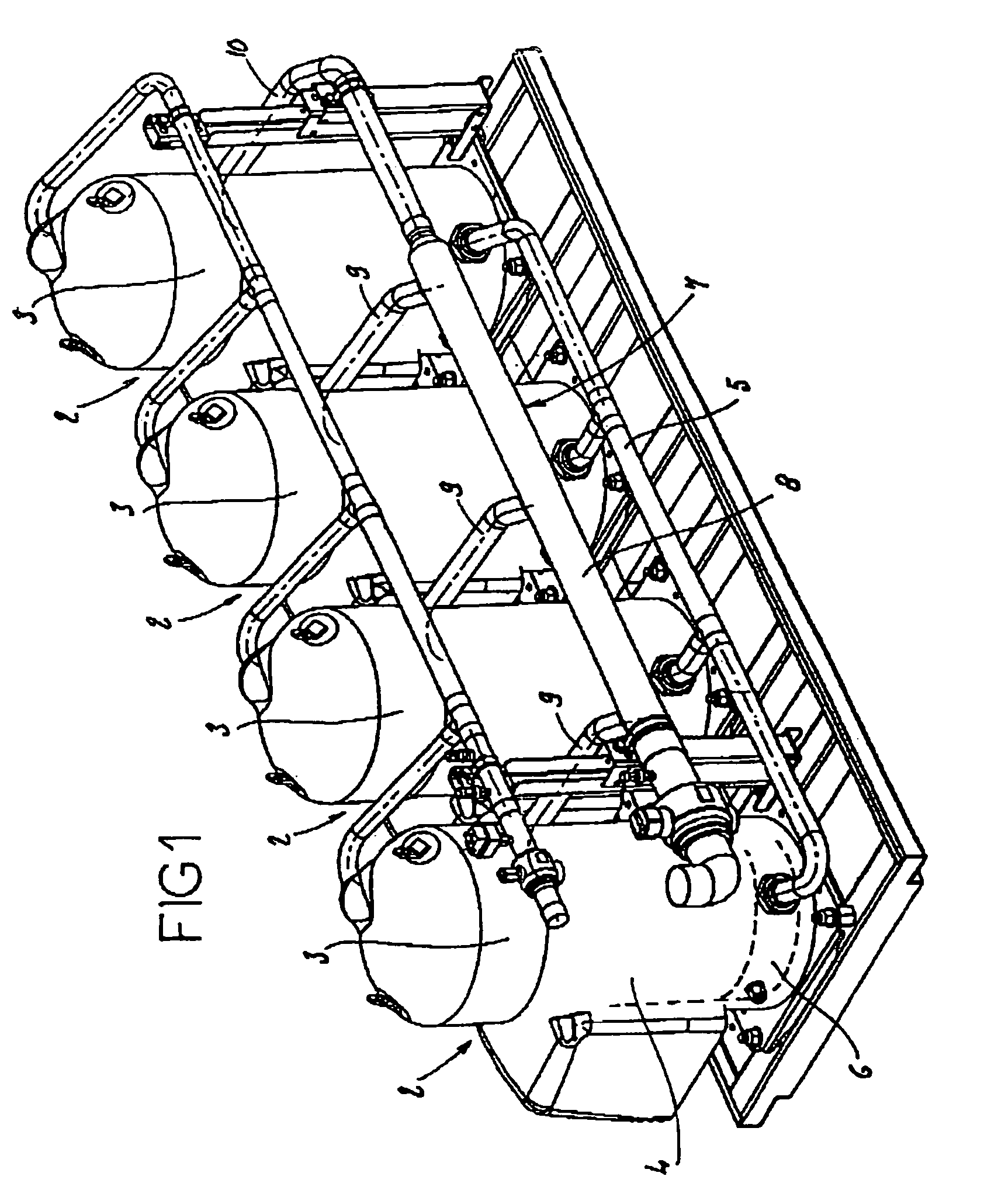
[0038]FIG. 1 describes an arrangement of compressors in parallel, including:[0039]four refrigeration compressors, each having a body 3 delimiting an inside space 4;[0040]an oil level equalization tube 5 providing communication between the oil pans 6 provided in the body 3 of compressors 2; and[0041]a suction gas distribution device 7 comprising a substantially straight distribution tube 8 as well as branch tubes 9, 10 providing communication between the distribution tube 8 and the inside spaces 4 of the bodies of compressors 2.

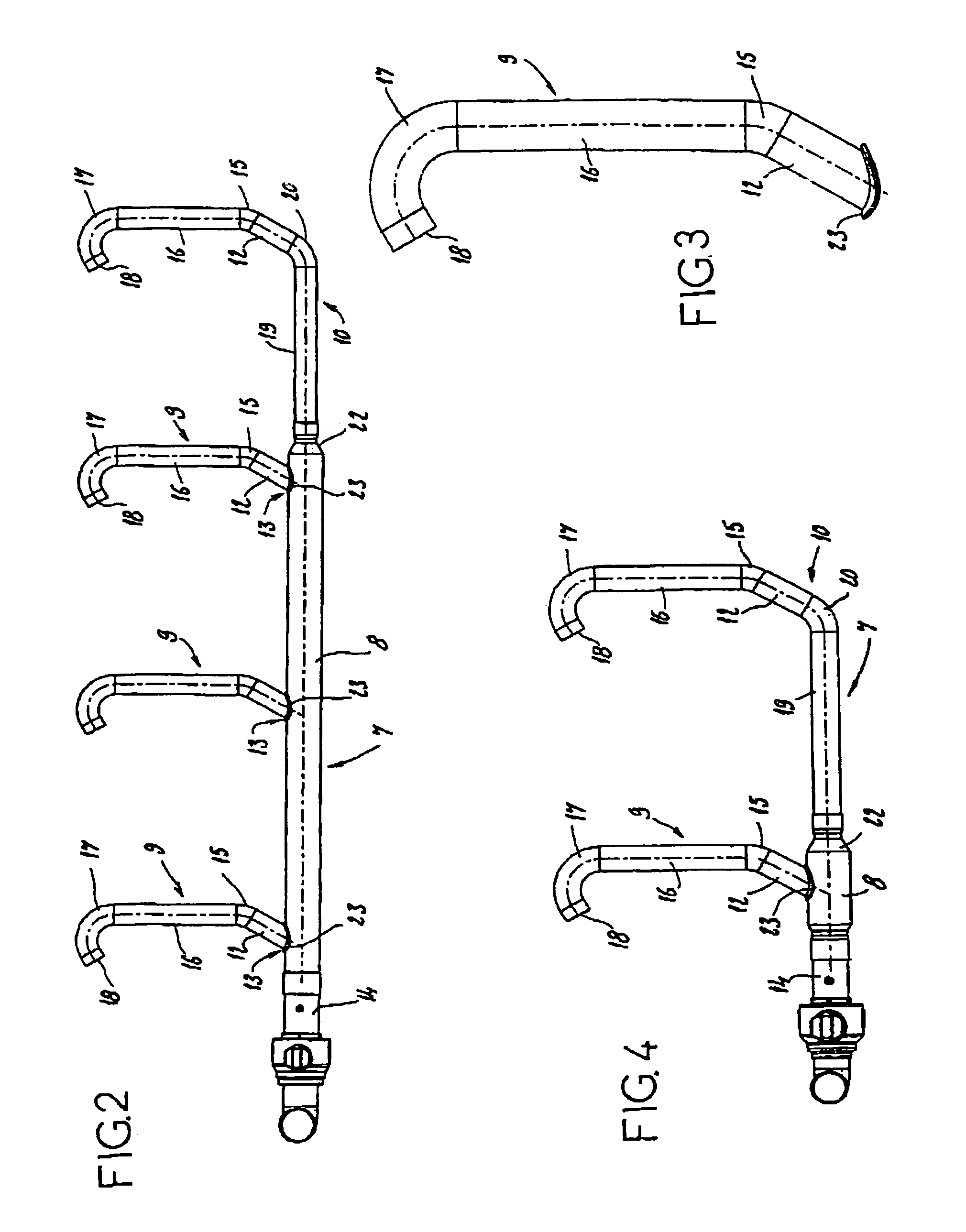
[0042]FIG. 2 shows the distribution device 7 according to a first embodiment for an arrangement of four compressors. The distribution tube 8 has, upstream of the first branch 13, a straight portion 14 that is about 330 mm long and has five to seven times the outside diameter of the distribution tube 8. In this embodiment, the outside diameter of the branch tubes 9 is essentially equal to 1⅝ inches (one inch being equal to 2.540 cm), the outside diameter of the...


PUM


Abstract

Device for distributing suction gas for a parallel compressor installation, said installation having at least two refrigeration compressors, at least one oil level equalization tube providing a communication between the oil pans provided in the bodies of the compressors, at least one suction gas distribution device comprising an essentially straight distribution tube, and branch tubes. The branch tubes have at least one portion forming an angle of between 55° and 65° with the axis of the distribution tube. The present invention uses a special geometry for equalizing the pressures in the oil pans of each compressor and thus using simple equalization channels.

Description

BACKGROUND OF THE INVENTION[0001]1. Field of Invention[0002]The present invention relates to a suction gas distribution device for parallel compressor installations.[0003]At least four constraints must be borne in mind when several refrigeration compressors are operated in parallel:[0004]apportioning the oil levels in each compressor;[0005]reducing pressure losses at the suction end in order to maximize the performance factor;[0006]maintaining a minimum flowrate in the pipe to create shear forces that push the oil covering the walls to the compressors; and[0007]total piping cost.[0008]2. Description of Related Art[0009]The present state of the art offers several existing solutions.[0010]Compressors are often arranged in parallel in refrigeration applications. Oil apportioning systems in this case are complex and expensive, based on combining common oil collectors, devices for measuring individual levels, and solenoid distribution valves. These systems are prohibitively expensive in ...

Claims


Application Information

Patent Timeline
Patent Type & Authority Patents(United States)
IPC IPC(8): F25B43/02F04B39/02F04B41/06F25B31/00F25B41/00
CPCF25B31/002F25B41/003F25B2400/075F25B41/40F04C23/008F04C29/02F04C18/0215F04C18/16F04C23/001F04C2240/806
Inventor DE BERNARDI, JEANEUTHINE, MICKAEL
Owner DANFOSS COMML COMPRESSORS
Why Eureka
Try Eureka