
Method of providing hydraulic/fiber conduits adjacent bottom hole assemblies for multi-step completions

a technology of hydraulic/fiber conduits and bottom hole assemblies, which is applied in the direction of connection contact member materials, borehole/well accessories, survey, etc., can solve the problems of inability to work with auxiliary conduits as they are put together at the surface, inability to access previously known devices, and inability to develop techniques in the past to allow that to occur

Inactive Publication Date: 2006-01-10
BAKER HUGHES INC
View PDF38 Cites 276 Cited by
  • Summary
  • Abstract
  • Description
  • Claims
  • Application Information

AI Technical Summary

Benefits of technology

[0006]Accordingly, it is the objective of the present invention to provide a method whereby auxiliary conduits can be instrumental in the performance of various operations essential to the completion as well as to provide data on a real-time basis of

Problems solved by technology

Due to the multi-stage nature of such operations, prior techniques for mounting auxiliary conduits to the assembly as it is put together at the surface were not workable.
As previously stated, where the completion requires multiple steps and trips into the well bore, if auxiliary conduits are to be provided to the producing zone, techniques in the past have not been developed to allow that to occur.
However, in situations involving multi-trip operations such as a gravel packing a well, such access was unavailable in the previously known devices.
However, running these tools required interruption of production.
While these tools provided data, it was only discrete snapshots of the production environment and such information was often provided at a significant direct and indirect cost.

Method used


Image

  • Method of providing hydraulic/fiber conduits adjacent bottom hole assemblies for multi-step completions
  • Method of providing hydraulic/fiber conduits adjacent bottom hole assemblies for multi-step completions
  • Method of providing hydraulic/fiber conduits adjacent bottom hole assemblies for multi-step completions

Examples


Embodiment Construction

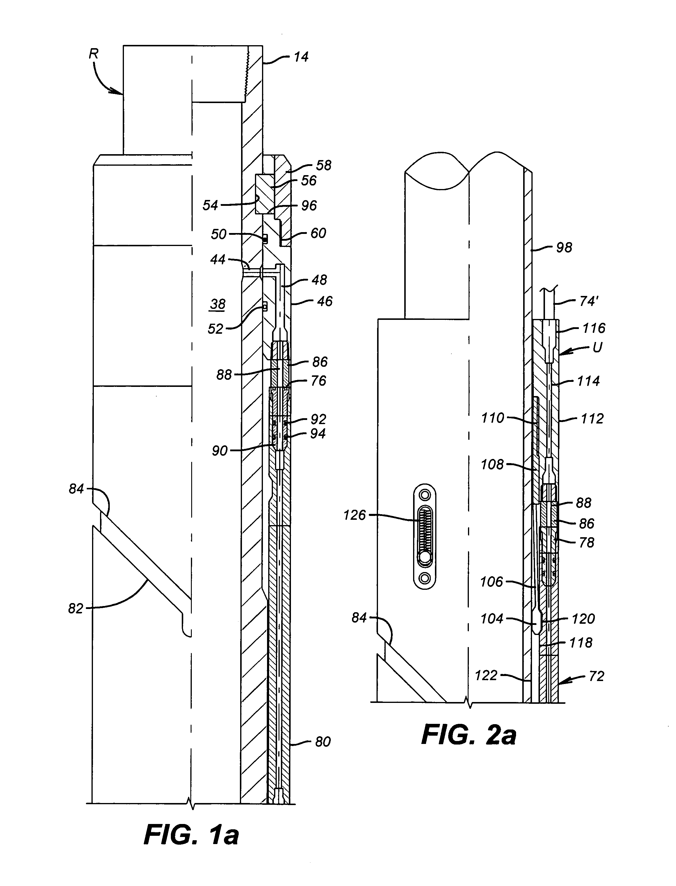
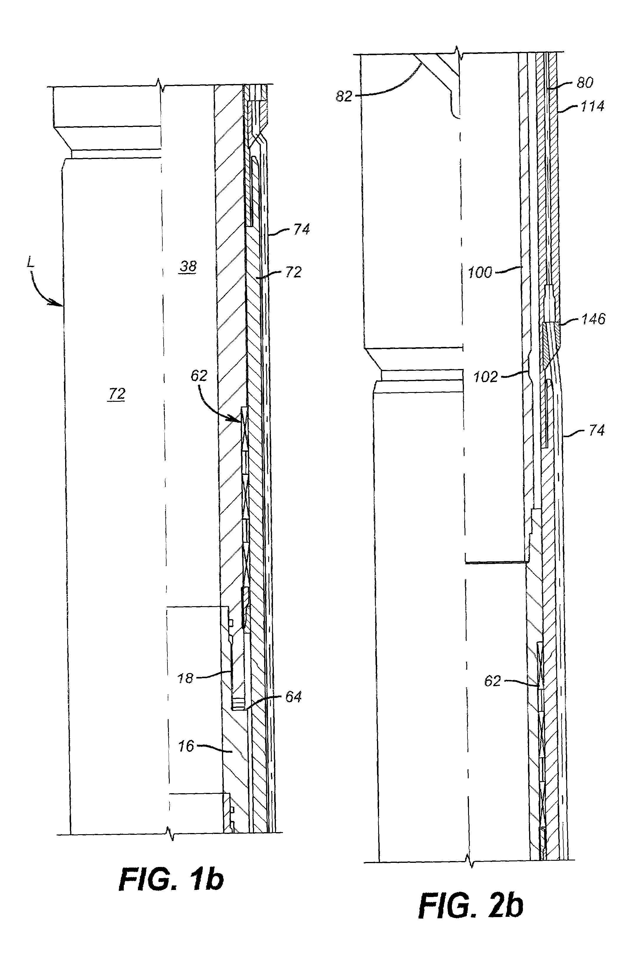
[0030]The preferred embodiment of the method of the present invention relates to the ability to place auxiliary conduits or / and fiber optics near gravel pack screens. Those skilled in the art will appreciate that other applications for auxiliary conduits adjacent the producing formation are within the scope of this invention. Most applicable are multi-trip completion procedures where there is still a need for real time communication to the surface from the zone where the completion is taking place or where ultimately the production continues, or below.

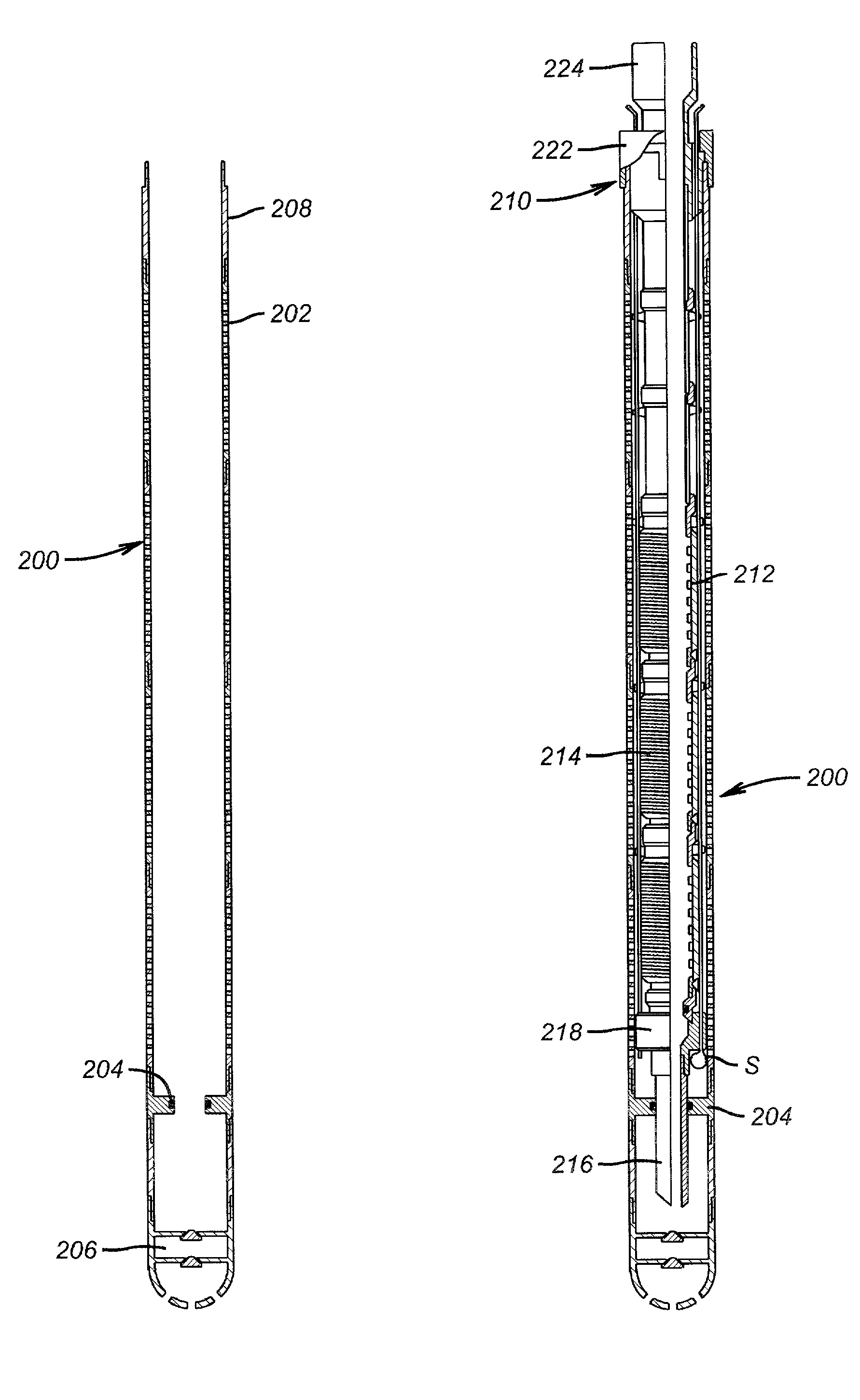
[0031]In the preferred embodiment, a shroud assembly 200 shown in FIG. 12 is used. The shroud assembly is a pipe assembled in sections which has perforations 202 and an O-ring seal sub 204 near the lower end. Additionally, a set shoe 206 completes the shroud assembly 200. A landing nipple 208 is at the top of the shroud assembly 200 and is used for a quick connect to the screen assembly 210 shown in FIG. 14a. The detail of this quick c...


PUM


Abstract

A technique for providing auxiliary conduits in multi-trip completions is disclosed. The technique has particular applicability to liner mounted screens which are to be gravel packed. In the preferred embodiment, a protective shroud is run with the gravel pack screens with the auxiliary conduits disposed in between. The auxiliary conduits terminate in a quick connection at a liner top packer. The gravel packing equipment can optionally be secured in a flow relationship to the auxiliary conduits so as to control the gravel packing operation. Subsequent to the removal of the specialized equipment, the production tubing can be run with an auxiliary conduit or conduits for connection down hole to the auxiliary conduits coming from the liner top packer for a sealing connection. Thereafter, during production various data on the well can be obtained in real time despite the multiple trips necessary to accomplish completion. The various completion and / or production activities can also be accomplished using the auxiliary conduits such as actuation of down hole flow control devices, chemical injection, pressure measurement, distributed temperature sensing through fiber optics, as well as other down hole parameters.

Description

CROSS REFERENCE TO RELATED APPLICATION[0001]This nonprovisional U.S. Application claims the benefit of provisional application No. 60 / 174,412, filed on Jan. 5, 2000.FIELD OF THE INVENTION[0002]The field of this invention comprises methods of allowing the provision of conduits which can carry the power, signal, hydraulic, pressure, fiber optic cable, and other means of communication down to a bottom hole assembly where the completion requires multiple trips.BACKGROUND OF THE INVENTION[0003]In certain types of completions, a bottom assembly such as, for example, gravel pack screens are assembled as part of the liner and a liner top packer and installed in the well bore. Various operations thereafter occur involving specialized equipment. For example, cementing the liner and gravel packing the screens. After the completion of such steps with specialized equipment, the production string is then tagged into the liner-top packer so that production can begin. Due to the multi-stage nature ...

Claims


Application Information

Patent Timeline
IPC IPC(8): E21B43/04E21B23/03E21B43/08E21B17/00E21B17/02E21B47/12
CPCE21B17/003E21B47/12E21B43/08E21B17/026
Inventor BAYNE, CHRISTIAN F.VOLL, BENN A.BROOME, J. TODDZACHMAN, JAMES R.FALCONER, GRAEME H.NORRIS, MICHAEL W.ZISK, JR., EDWARD J.BILBERRY, DAVID A.HODGES, STEVE B.
Owner BAKER HUGHES INC
Learn More