Ink jet record head

a jet recorder and jet recorder technology, applied in printing and other directions, can solve the problems of pressure loss, adverse discharge effects, and prone to being seen, and achieve the effects of reducing effects, low cost, and low cos

Inactive Publication Date: 2006-01-10
CANON KK
View PDF24 Cites 28 Cited by
  • Summary
  • Abstract
  • Description
  • Claims
  • Application Information

AI Technical Summary

Benefits of technology

[0010]Incidentally, as for the record head described above, when discharging the ink, the flow of the ink filled in the bubbling chamber is divided into the discharge port side and the supply path side by the bubbles growing in the bubbling chamber. At that time, a pressure due to bubbling of a fluid slips away to the supply path side, or a pressure loss occurs due to friction with an inner wall of the discharge port. This phenomenon causes adverse effects on discharge, and it tends to become conspicuous as a liquid droplet becomes smaller. To be more specific, as a discharge caliber is rendered smaller in order to make a small liquid droplet, resistance of a first discharge port portion becomes extremely high so that a flow rate in the discharge port direction decreases and the flow rate in the flow path direction increases, resulting in reduced discharge speed of the ink droplet. It is possible, as a means for solving this problem, to provide a second discharge port portion whose cross-sectional area vertical to the flow is larger than the discharge port and thereby to lower the entire flow resistance in the discharge port direction so that bubbling grows with less pressure loss in the discharge port direction. Thus, it is feasible to curb the flow rate slipping away in the flow path direction and prevent the reduction in the discharge speed of the ink droplet.
[0014]In consideration of the problem in the above-mentioned actuality, a first object of the present invention is to provide an ink jet record head having a nozzle shape capable of reducing effects of the thickening of the ink in the discharge port portion during standby, possessing good discharge characteristics, promptly curbing meniscus vibrations occurring on refilling, and stably discharging the ink.
[0015]A second object of the present invention is to provide the ink jet record head in the nozzle shape capable of curbing the above-mentioned variations in the discharge volume due to thermal storage of the ink.
[0017]It is possible, by the above-mentioned record head structure, to provide an ink jet head capable of reducing the effects due to the thickening of the ink in the discharge port portion during standby, recording an image having few variations in the discharge characteristics and possessing high definition. It can also curb the meniscus vibrations. To be more specific, when the liquid rushes in the discharge port direction while refilling, a liquid flow close to a wall surface of the above-mentioned second discharge port portion is bent along a curved portion and has a flow rate for colliding almost vertically with a refilling mainstream in a direction vertical to the above described element substrate so that a rush speed into the discharge port of the refilling mainstream in the direction vertical to the above described element substrate is reduced so as to consequently attenuate the meniscus vibrations (refer to FIG. 6, illustrating a schematic sectional view similar to FIGS. 2B, 3B, 4B and 5B).
[0018]Furthermore, in the case of successively discharging at the high frequency, the minute stagnant areas of the ink having almost no flow speed become smaller in the flow in the discharge port direction after the bubbling. Consequently, the thermal storage of the ink is held down on successive discharge operations by an electrothermal converting element so that there will be fewer variations in the volume of discharged liquid droplets.
[0019]According to the present invention, the second discharge port portion is curved so that the thickness between the surface of a flow path composition member and a ceiling surface of the second discharge port portion is kept relatively thick so as to increase strength.

Problems solved by technology

At that time, a pressure due to bubbling of a fluid slips away to the supply path side, or a pressure loss occurs due to friction with an inner wall of the discharge port.
This phenomenon causes adverse effects on discharge, and it tends to become conspicuous as a liquid droplet becomes smaller.
However, it is not desirable in the case of discharging the above-mentioned minute liquid droplet because a throughput is thereby extremely reduced.
It is because such stagnation of the ink may cause variations in discharge volume in the case where the discharge is successively performed at a high frequency.

Method used


Image

  • Ink jet record head
  • Ink jet record head
  • Ink jet record head

Examples


first embodiment

(First Embodiment)

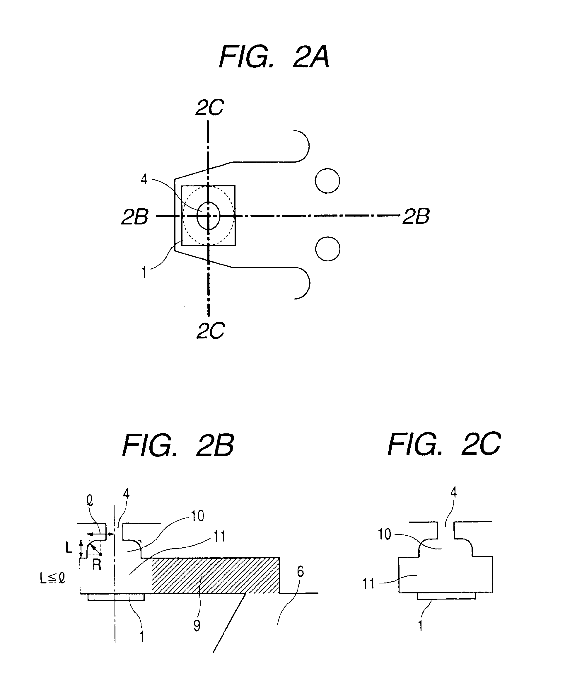
[0035]FIGS. 2A, 2B and 2C show the nozzle structure of the ink jet record head according to a first embodiment of the present invention. FIG. 2A is a plan perspective view for viewing one of the plurality of nozzles of the ink jet record head from a vertical direction to a substrate, FIG. 2B is a sectional view along a line 2B—2B in FIG. 2A, and FIG. 2C is a sectional view along a line 2C—2C in FIG. 2A.

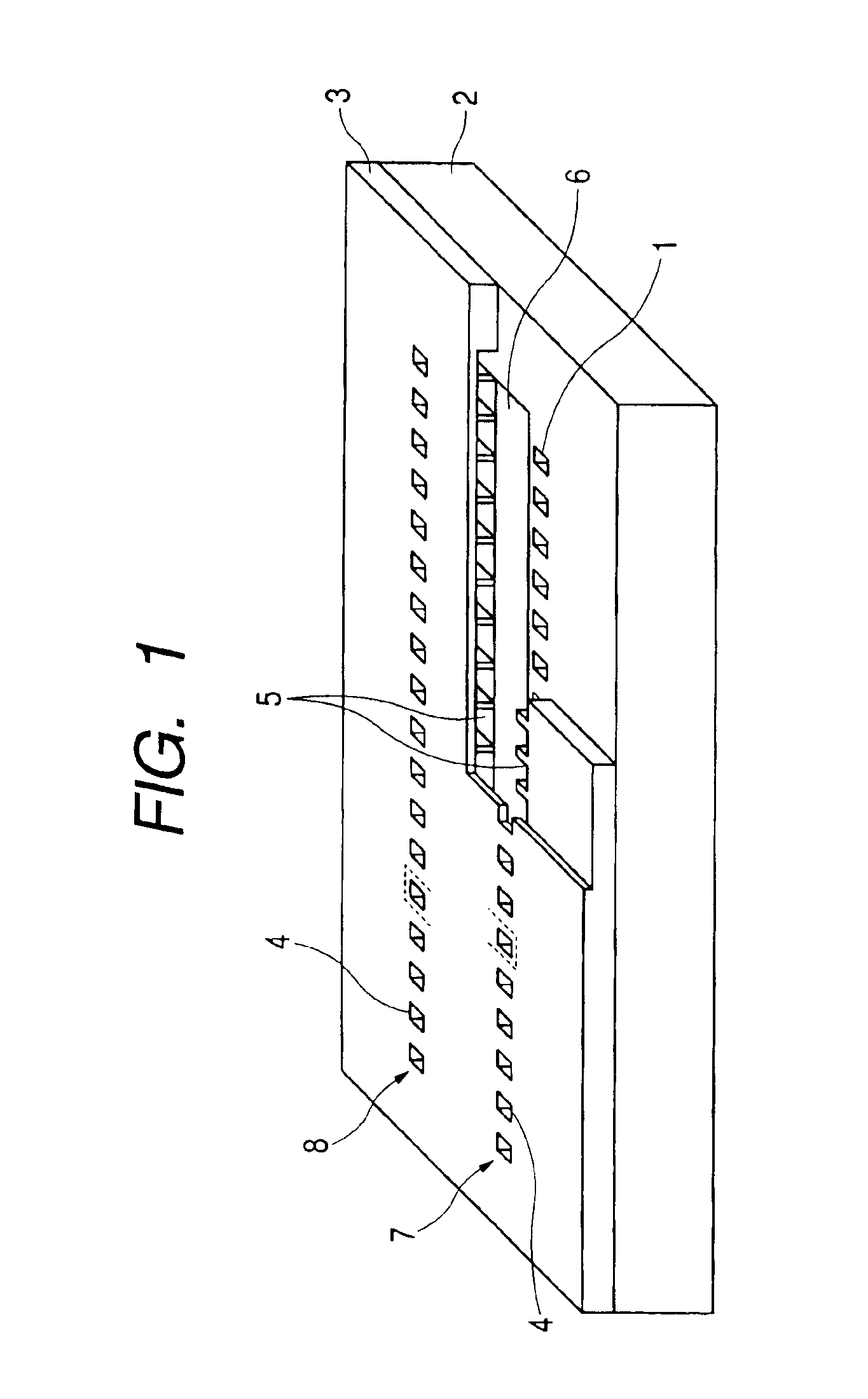
[0036]As shown in FIG. 1, the record head having the nozzle structure in this form is equipped with an element substrate 2 on which the plurality of heaters 1 which are the electrothermal converting elements are provided and a flow path composition substrate 3 stacked on and joined with a principal surface of the element substrate 2 to constitute a plurality of flow paths of the ink.

[0037]The element substrate 2 is formed by glass, ceramics, resin, metal and so on for instance, and is generally formed by Si. On the principal surface of the element substrate 2, the he...

second embodiment

(Second Embodiment)

[0049]Here, the differences from the first embodiment will be mainly described based on FIGS. 3A, 3B and 3C.

[0050]FIGS. 3A, 3B and 3C show the nozzle structure of the ink jet record head according to a second embodiment of the present invention. FIG. 3A is a plan perspective view for viewing one of the plurality of nozzles of the ink jet record head from the vertical direction to the substrate, FIG. 3B is a sectional view along a line 3B—3B in FIG. 3A, and FIG. 3C is a sectional view along a line 3C—3C in FIG. 3A.

[0051]As shown in FIG. 3B, the second discharge port portion 10 of the nozzle according to this embodiment has the form in which the angles on the upper side of the square are curved respectively on any cross section vertical to the principal surface of the element substrate (surface on which the heaters 1 are formed) and going through the center of the discharge port 4, and these curves are shaped as arcs of a circle of a radius R having its center on th...

third embodiment

(Third Embodiment)

[0060]Here, the differences from the first embodiment will be mainly described based on FIGS. 4A, 4B and 4C.

[0061]FIGS. 4A, 4B and 4C show the nozzle structure of the ink jet record head according to a third embodiment of the present invention. FIG. 4A is a plan perspective view for viewing one of the plurality of nozzles of the ink jet record head from the vertical direction to the substrate, FIG. 4B is a sectional view along a line 4B—4B in FIG. 4A, and FIG. 4C is a sectional view along a line 4C—4C in FIG. 4A.

[0062]As shown in FIG. 4B, the second discharge port portion 10 of the nozzle according to this embodiment has the form in which the angles on the upper side of the square are curved respectively on any cross section vertical to the principal surface of the element substrate (surface on which the heaters 1 are formed) and going through the center of the discharge port 4, and these curves are shaped as arcs of a circle of a radius R inscribed in the angles o...


PUM


Abstract

To provide an ink jet record head having a nozzle shape capable of promptly curbing meniscus vibrations occurring on refilling and stably performing discharge.A second discharge port portion 10 has a form in which, with a lower side of a square on a bubbling chamber 8 side, angles on an upper side of the square are curved respectively on any cross section vertical to a principal surface of an element substrate on which heaters 1 are formed and going through the center of a discharge port 4, and these curves are shaped as arcs of circles of a radius R inscribed in the angles on the upper side of the square respectively.

Description

BACKGROUND OF THE INVENTION[0001]1. Field of the Invention[0002]The present invention relates to a liquid discharge head for discharging a liquid droplet such as an ink droplet and performing recording on a recording medium, and in particular, to the liquid discharge head for performing ink jet recording.[0003]2. Related Background Art[0004]An ink jet recording system is one of so-called non-impact recording systems. As for the ink jet recording system, noise generated on recording is almost negligible and high speed recording is possible. The ink jet recording system is capable of recording on various recording media and fixing ink on so-called standard paper without requiring a special process, and in addition, it allows a high-definition image to be obtained at a low price. Because of these advantages, the ink jet recording system is rapidly becoming widespread in recent years not only for a printer as a peripheral of a computer but also as a means of recording of a copying machi...

Claims


Application Information

Patent Timeline
Patent Type & Authority Patents(United States)
IPC IPC(8): B41J2/05B41J2/00B41J2/14
CPCB41J2/1404B41J2/1433B41J2002/14403B41J2002/14387B41J2002/14169B41J2/00
Inventor TOMIZAWA, KEIJIMURAKAMI, SHUICHI
Owner CANON KK
Why Eureka
Try Eureka