Corner connection for temporary shoring

a corner connection and temporary shoring technology, applied in the direction of shaft equipment, shaft lining, artificial islands, etc., can solve the problems of insufficient maximum permissible load and always a factor in the cost of using heavier materials, and achieve the effect of greater loads

Active Publication Date: 2006-01-10
MEYER JOHN HENRY +1
View PDF29 Cites 9 Cited by
  • Summary
  • Abstract
  • Description
  • Claims
  • Application Information

AI Technical Summary

Problems solved by technology

However even with this reinforcing bar 120 in place the maximum permissible load may be insufficient and the expense of using heavier materials is always a factor.

Method used


Image

  • Corner connection for temporary shoring
  • Corner connection for temporary shoring
  • Corner connection for temporary shoring

Examples


Embodiment Construction

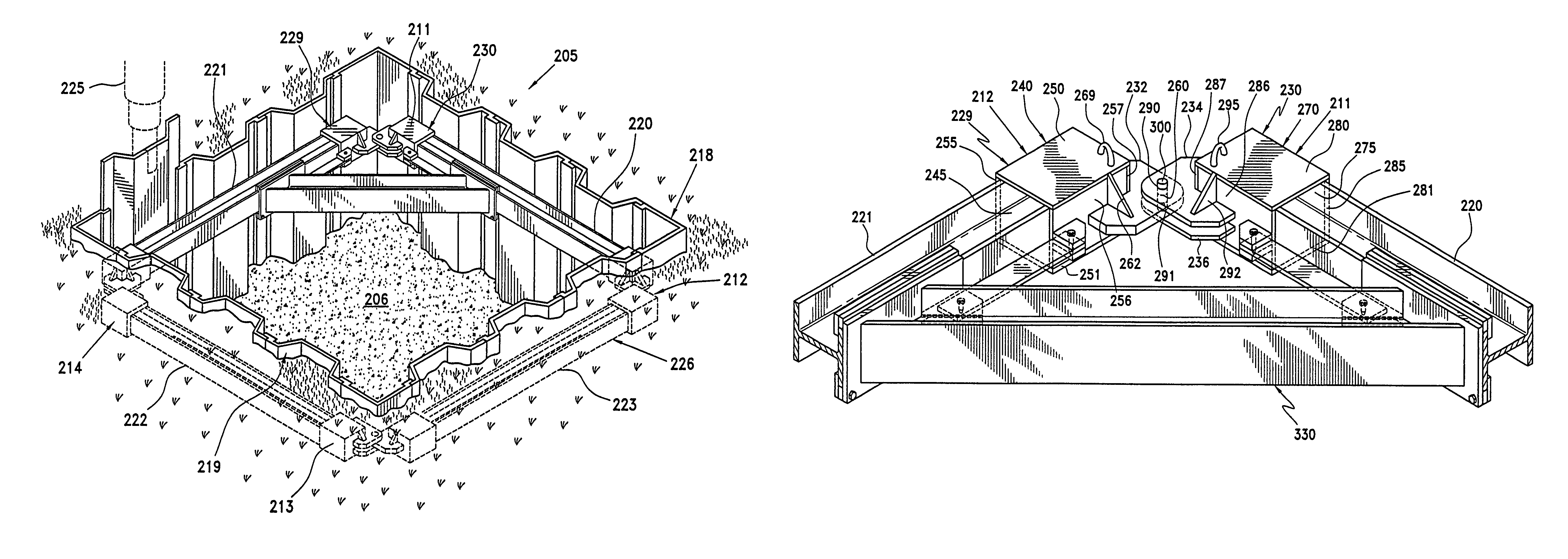
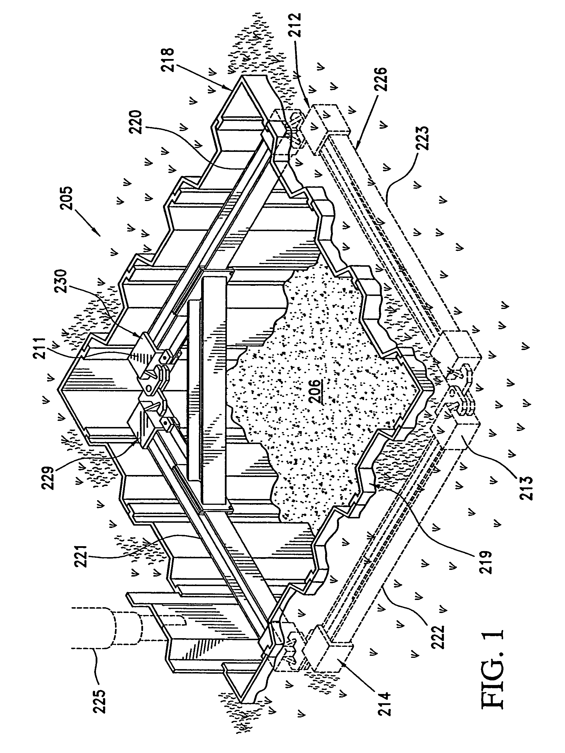
[0026]Referring now to FIG. 1 there is shown a typical excavation site 205 with an excavation hole 206 incorporating corner connections 211–214 for temporary shoring 218 according to a preferred embodiment of the invention. The temporary shoring 218 actually comprises three major elements: interlocking sheet piling 219, reinforcing I-beams or shoring beams 220–223 and corner connections 211–214, each connection including two connectors for the I-beams 220–223. Although shown here as I-beams, beams of different shapes could be used so long as the connector and beam have mating shapes. For example, round, L-shaped and U-shaped beams could be used, as could a beam of almost any cross section. Interlocking sheet piling 219 is shown placed along the walls of the excavation hole 206. Such interlocking sheet piling 219, which in the embodiment shown is formed by interconnecting two types of side wall panels and corner panels (not separately labeled), is usually driven into the ground prior...


PUM


Abstract

A corner connection used to secure I-beams together at corners within the excavation site is provided with a reinforcing assembly that allows for greater loads. Typically, four I-beams are connected together to form a rectangular frame that is suspended within the excavation for bracing the shoring walls thereof; however, any polygonal shape may be used. The corner connection itself comprises mating socket or connecting members that are placed over the ends of I-beams to be fastened together. One of the connecting members includes an outwardly extended tab while the other includes a pair of outwardly extended tabs. The first outwardly extending tab fits between the two extending tabs of the corresponding connecting member. All of the tabs are provided with apertures that are placed in alignment when the connection is made so that a bolt or pin can be passed through the apertures to secure the two connectors together. An additional set of tabs is provided on the connecting members that is also provide with apertures. A reinforcing assembly is provided and includes a reinforcing bar with tabs. A first spacer bar is attached to the reinforcing bar and one connecting member and a second spacer bar is attached to the reinforcing bar and an adjacent connecting member. The spacer bars, the reinforcing bar and the connection members are all connected with tab / pin connections. Advantageously the reinforcing assembly can use the existing second set of tabs located on the prior art connectors. Such an arrangement provides much greater support for the sidewalls of the excavation site.

Description

BACKGROUND OF THE INVENTION[0001]1. Field of the Invention[0002]The present invention is generally directed to a system for temporarily shoring up an excavation site. More particularly the invention is directed to a reinforcing assembly for a corner connection used in a reinforcing arrangement that supports sheet piling in an excavation site.[0003]2. Description of the Prior Art[0004]In a typical excavation site, workers are exposed to numerous hazards. The most common hazard is having the walls of the excavation site cave in on the workers, thus causing serious injury. Often due to soil conditions and wetness, the sides of a construction site will simply collapse. Water is a particularly dangerous hazard because it is so heavy and can destroy shoring, which has not been properly reinforced. Realizing this problem the government, at both the federal and state level, has set up specific requirements for all excavation sites to avoid the problem of cave-ins. For example the United Sta...

Claims


Application Information

Patent Timeline
Patent Type & Authority Patents(United States)
IPC IPC(8): E02D17/04
CPCE02D17/04
Inventor MEYER, JOHN HENRYMEYER, JOHN WAYNE
Owner MEYER JOHN HENRY
Why Eureka
Try Eureka