Safety switch

Inactive Publication Date: 2006-01-10
LU CHEN DUNG
View PDF4 Cites 7 Cited by
  • Summary
  • Abstract
  • Description
  • Claims
  • Application Information

AI Technical Summary

Benefits of technology

[0004]Accordingly, the primary object of the present invention is to provide a safety switch, wherein the safety switch has a simple structure and i

Problems solved by technology

However the structure is complicated, has too many parts, so t

Method used


Image

  • Safety switch
  • Safety switch
  • Safety switch

Examples


Example

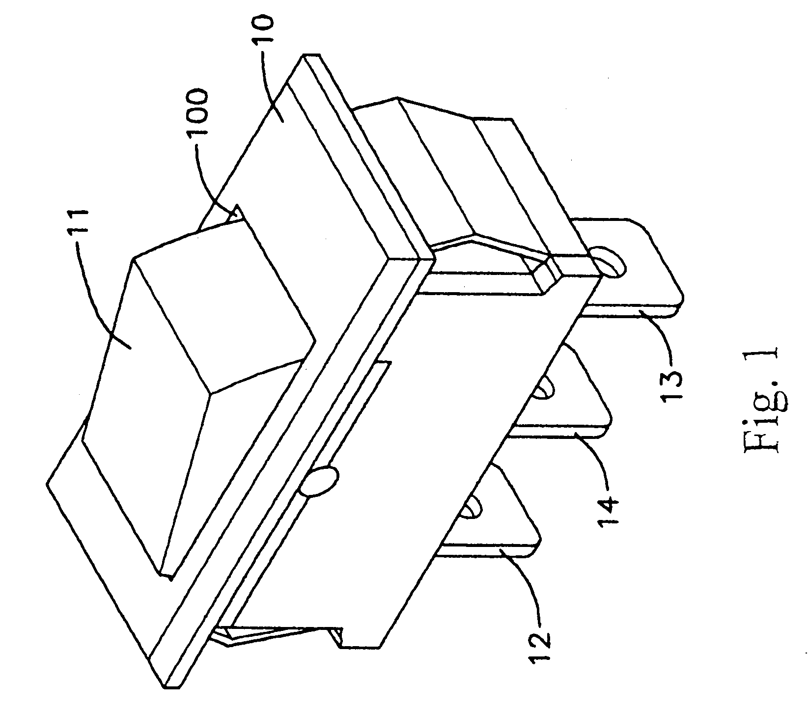
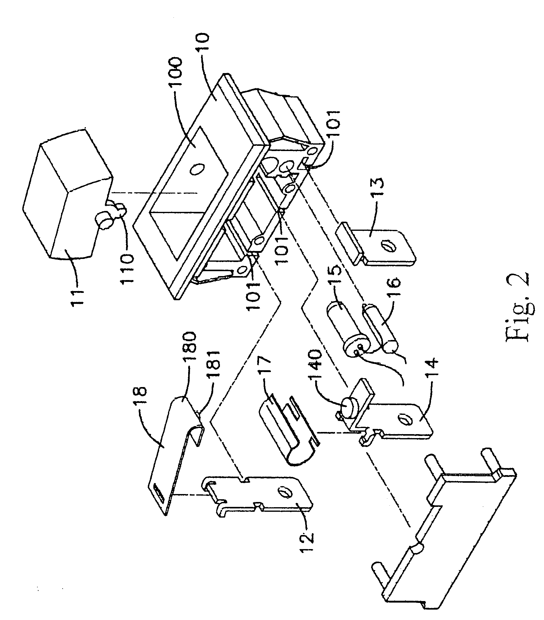
[0025]With reference to FIGS. 1 to 3, the first embodiment of the present invention has the following elements.

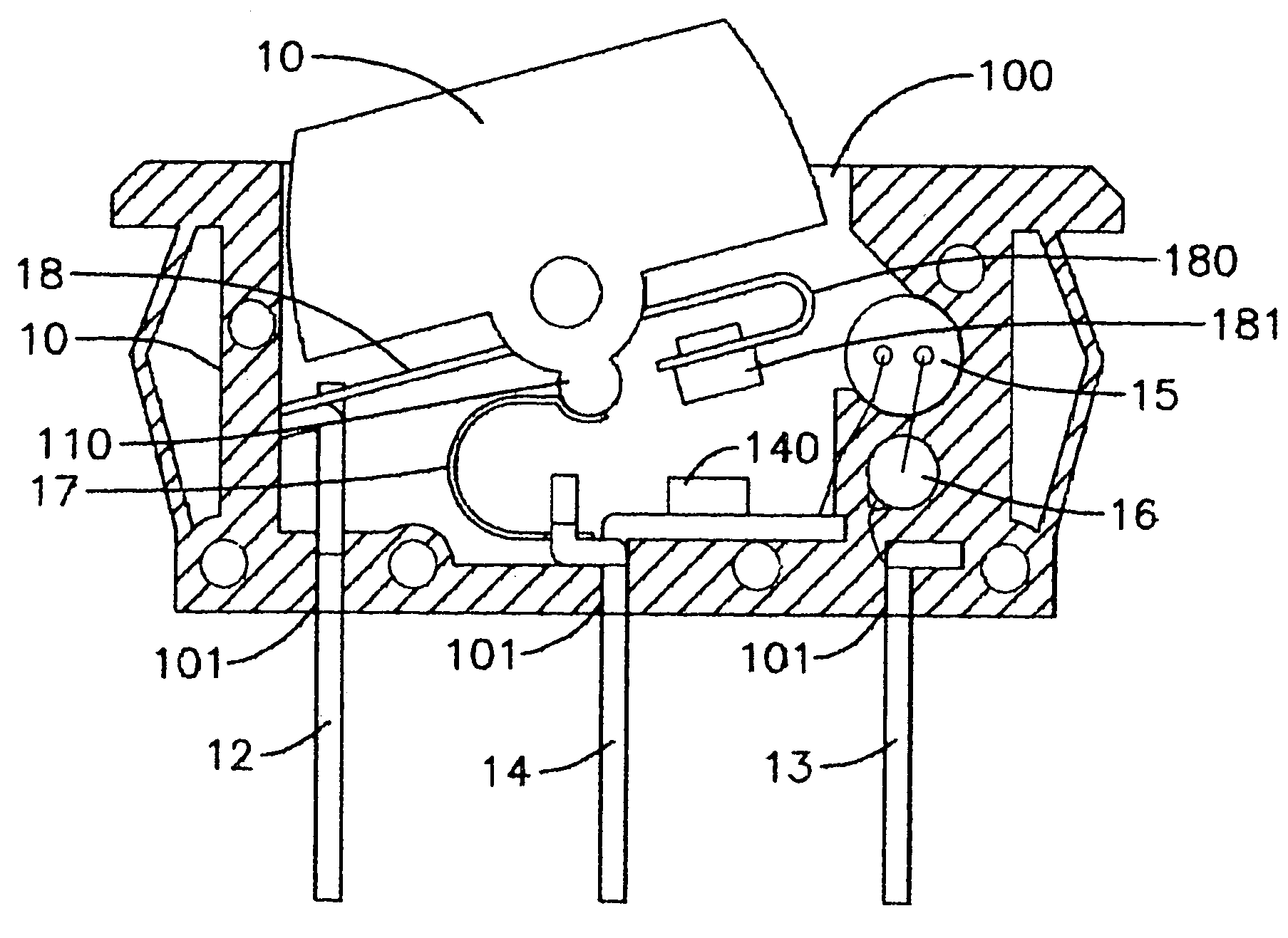
[0026]A hollow body 10 has an opening100 at an upper end thereof and a lower end of the hollow body 10 has three slots 101 which are spaced arranged.

[0027]A button 11 is pivotally installed upon the opening 100 of the hollow body 10. A press block 110 downwards extends from a pivotal point of the button 11.

[0028]A first power terminal 12 is installed at one slot of the three slots 101.

[0029]A second power terminal 13 is installed at another slot of the three slots 101.

[0030]A load terminal 14 is installed at the other slot of the three slots 101 which is located between the first power terminal 12 and the second power terminal 13. The load terminal 14 is electrically connected to the second power terminal 13 through a neon bulb 15 and a resistor 16. An upper side of the load terminal 14 is installed with an electric silver sheet 140.

[0031]An elastomer 17 is a U shape metal ...

Example

[0036]Referring to FIGS. 6 and 7, the second embodiment of the present invention is illustrated. The difference of the second embodiment from the first embodiment is that one end of the metal sheet 18 connected to the first power terminal 12 has no U shape structure. The conductive silver sheet 181 is directly installed on the metal sheet 18 at a position corresponding to that of the electric silver sheet 140. If the current overloads, the connection of the metal sheet 18 and the first power terminal 12 will deform so that the metal sheet 18 curls upwards to drive the button 11 to eject upwards. Thereby by the action of the elastomer 17 and the press block 110, the same effect of the first embodiment is achieved.

[0037]Referring to FIGS. 8 and 9, the second embodiment of the present invention is illustrated. The difference of the third embodiment from the second embodiment is that one end of the metal sheet 18 has the conductive silver sheet 181 which is bent toward the button so as ...


PUM


Abstract

A safety switch comprises a hollow body having an opening and a lower end of the hollow body having three slots; a button pivotally installed upon the opening; a first power terminal installed at one of the three slots; a second power terminal installed at another of the three slots; a load terminal installed at the other slot of the three slots; an elastomer being a U shape metal piece; one end of the elastomer being buckled to an upper end of the load terminal and another end thereof being buckled to the press block of the button; and a metal sheet being installed at a lower side of the button; the metal sheet being made of a compound metal having materials of different expansion coefficients; one end of the metal sheet being connected to the a power terminal; and another end thereof being installed with a conductive silver sheet.

Description

FIELD OF THE INVENTION[0001]The present invention relates to switches, and particularly to a safety switch, wherein the safety switch has a simple structure and is made of a fewer elements. Thereby the manufacturing process is simplified. The fault rate of the safety switch is reduced.BACKGROUND OF THE INVENTION[0002]A safety switch is used in electric devices for interrupting the power connection as overloading so as to protect the device to be in safety condition.[0003]Most of the prior art safety switch can achieve the effect of turning off power so as to prevent fire accident. However the structure is complicated, has too many parts, so that a large amount of parts are necessary. Thereby cost is high. All these are main concern in the manufacturing of safety switch.SUMMARY OF THE INVENTION[0004]Accordingly, the primary object of the present invention is to provide a safety switch, wherein the safety switch has a simple structure and is made by a fewer elements. Thereby the manuf...

Claims


Application Information

Patent Timeline
IPC IPC(8): H01H71/16
CPCH01H73/14
Inventor LU, CHEN DUNG
Owner LU CHEN DUNG
Why Eureka
Try Eureka