Conditioning circuit for a power supply at the maximum power point, a solar generator, and a conditioning method

a technology of conditioning circuit and power supply, applied in the field of power supplies, can solve the problems of short circuit of some cells, severe constraint on the battery, and aging of the cells and deterioration of the cells caused by the environmen

Inactive Publication Date: 2006-01-10
ALCATEL LUCENT SAS
View PDF8 Cites 433 Cited by
  • Summary
  • Abstract
  • Description
  • Claims
  • Application Information

AI Technical Summary

Problems solved by technology

This problem is particularly acute in the case of solar generators used in satellites, for which the voltage V0 at which the power supplied by the solar generator is at a maximum varies as a function of the temperature to which the solar generator is subjected, as shown in FIG. 1; the voltage V0 also varies as a function of:the intensity of the solar radiation to which the generator is exposed, andaging of the generator.
Aging of the generator causes the short circuiting of some cells.
Thus one of the major difficulties to be overcome in predicting the optimum operating point lies in the dependence of the power delivered by a solar generator on parameters such as the incident solar energy, which is a function of the position of the cells relative to the light rays, the temperature of cells exposed to sunlight but dissipating energy by reflection and conduction toward the shaded rear surface, and, finally, aging of the cells and deterioration thereof caused by the environment, such as microcracks and meteorite impacts.
Another problem relates to the nature of the parameter to be optimized, i.e. the electrical power, which cannot be sensed directly.
This type of use represents a severe constraint on the battery, which must be recharged rapidly at high currents over short periods.
The technical difficulty lies in managing the division of these magnitudes.
This approach does not necessitate sampling.
The above MPPT solving methods have serious drawbacks.The most serious drawback of these methods is the necessity to insert between the solar generator and the load network units allowing independent evolutions of their potentials.
This has two consequences: firstly, an increase of approximately 10% in the performance of the GS in terms of mass, volume and power, and evacuation of the power dissipated by the regulators, which is of the order of 1 kW for an 11 kW GS, which leads to the use of heat pipes with the associated mass and energy constraints.The major drawback of continuous tracking processes is the very necessity for continuous tracking, as their name indicates.
The problem with this prior art is therefore that of control interference.

Method used


Image

  • Conditioning circuit for a power supply at the maximum power point, a solar generator, and a conditioning method
  • Conditioning circuit for a power supply at the maximum power point, a solar generator, and a conditioning method
  • Conditioning circuit for a power supply at the maximum power point, a solar generator, and a conditioning method

Examples


Embodiment Construction

[0094]In the present application, items having identical or similar functions carry the same reference numbers.

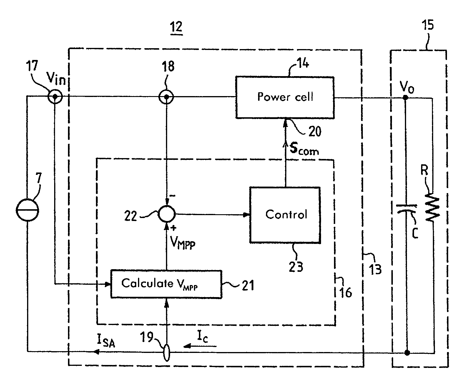
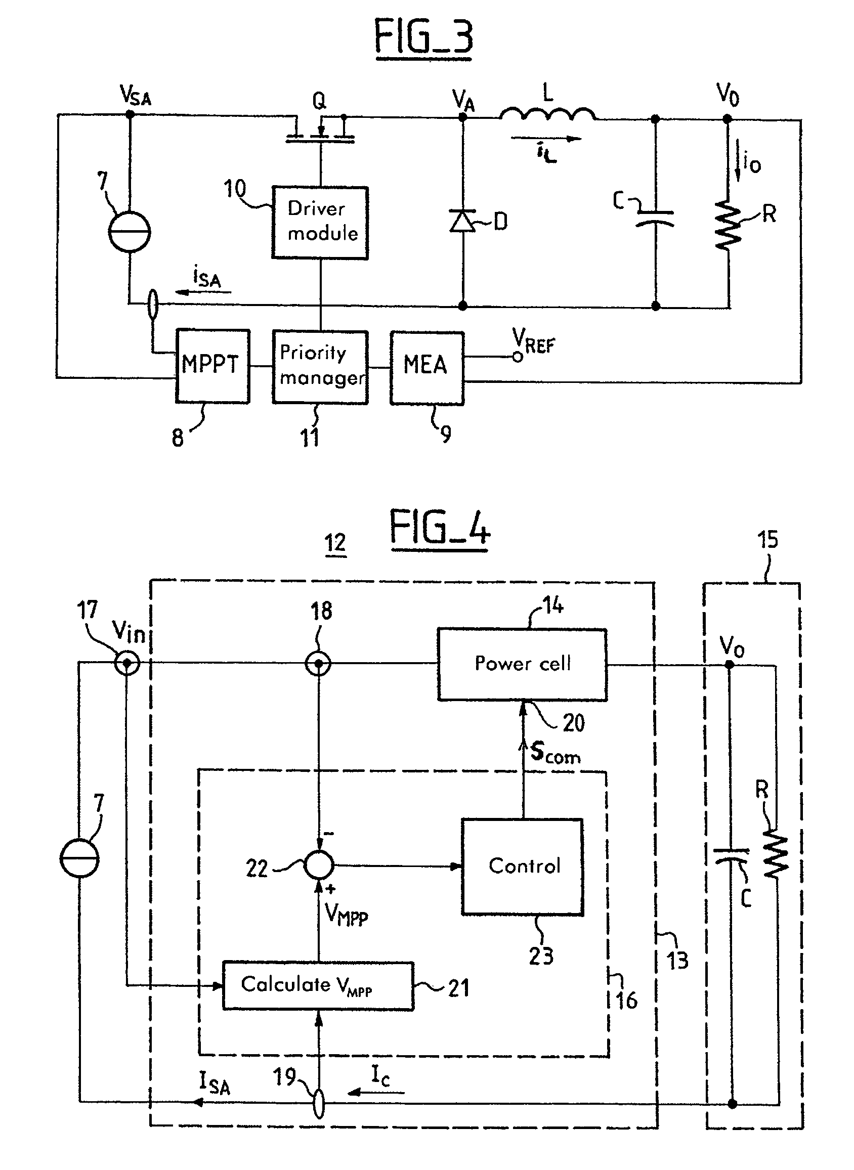
[0095]FIG. 4 is a diagrammatic representation of a system 12 incorporating a power supply, in this instance a solar generator 7, and a power conditioning circuit 13 conforming to one embodiment of the invention, in an application for supplying power to an RC load. The application could of course be oriented toward supplying power to a voltage bus of a satellite. The conditioning circuit enables the conditioned generator to deliver power at a fixed voltage V0, in other words to behave as a voltage source. The conditioning circuit also maximizes the power supplied by the solar generator.

[0096]FIG. 4 shows that the voltage Vin at the terminals of the solar generator is applied to the input of a power cell 14 (which can be a DC / DC converter) and is slaved to the MPP voltage.

[0097]The voltage V0 at the output of the power cell 14 is applied to an RC load 15; this usually include...


PUM


Abstract

The invention relates to a conditioning circuit that measures operating points of a power supply to deduce therefrom the current-voltage characteristic thereof and to determine directly the voltage corresponding to its maximum power point, without using any kind of tracking algorithm that causes the operating point of the power unit to oscillate about the maximum power point. The maximum power point voltage VMPP is supplied to a controller which regulates a power cell by slaving it to the input voltage until the output voltage of the supply is equal to the maximum power point voltage VMPP. The invention also relates to a solar generator and an associated conditioning method. One particular application is to high-power satellites.

Description

CROSS-REFERENCE TO RELATED APPLICATIONS[0001]This application is based on French Patent Application No. 02 11 597 filed Sep. 19, 2002, the disclosure of which is hereby incorporated by reference thereto in its entirety, and the priority of which is hereby claimed under 35 U.S.C. §119.BACKGROUND OF THE INVENTION[0002]1. Field of the Invention[0003]The present invention relates to power supplies and more precisely to the operation of power supplies for which the curve of the power supplied as a function of the voltage at the terminals of the supply features a maximum.[0004]For a power supply of the above kind, the power supplied is at a maximum when the voltage has a given value. For optimum use of the power supply—to draw maximum power therefrom—it is advantageous for the voltage at the terminals of the supply to be as equal to the aforementioned given value as often as possible.[0005]2. Description of the Prior Art[0006]The solar generators used for satellites constitute one example...

Claims


Application Information

Patent Timeline
Patent Type & Authority Patents(United States)
IPC IPC(8): G05F5/00G05F1/67
CPCG05F1/67Y10S323/906H02J7/35H02J2300/26Y02E10/56
Inventor CAPEL, ANTOINE
Owner ALCATEL LUCENT SAS
Why Eureka
Try Eureka