
Method and apparatus for providing a stable power output of power amplifiers, operating under unstable supply voltage conditions

a power amplifier and stable technology, applied in the field of power amplifiers, can solve the problems of reducing the overall efficiency of the power amplifier by 15%, the bulky and bulky built-in dc/dc converter, and the fluctuation of the feeding dc voltag

Inactive Publication Date: 2006-01-10
QUALCOMM INC
View PDF4 Cites 23 Cited by
  • Summary
  • Abstract
  • Description
  • Claims
  • Application Information

AI Technical Summary

Benefits of technology

[0013]Preferably, enhancement voltage is generated by determining a reference voltage, from which the enhancement voltage is derived and obtaining two control signals by amplifying the sampled instantaneous magnitude of the fluctuating output voltage and the enhancement voltage by the ratio between the reference voltage and the constant voltage level. The sum of the control signals is fed into the control input of the voltage enhancement circuitry, thereby causing the voltage enhancement circuitry to continuously amplify the reference voltage to a magnitude being the difference (Bmax−Bi) between the constant voltage level and the instantaneous value of the fluctuating output voltage.

Problems solved by technology

A major problem that frequently occurs in basestation is the fluctuations in the feeding DC voltage, caused by inadequate battery charging and by load variations.
This problem is apparent from practical requirements, which often define a range of supply voltage, for example, between 21 to 31 volts.
Conventional approaches for fulfilling such requirements employ high power built-in DC / DC converters which are bulky, expensive and power consuming.
Such high power built-in DC / DC converters reduce the overall efficiency of the power amplifiers by 15% (typically).
The approaches described above have not yet provided satisfactory solution to the problem of providing a stable power output to power amplifiers, operated with signals having a large peak-to-average ratio under unstable supply voltage conditions, while eliminating the need for DC input voltage stabilization.

Method used


Image

  • Method and apparatus for providing a stable power output of power amplifiers, operating under unstable supply voltage conditions
  • Method and apparatus for providing a stable power output of power amplifiers, operating under unstable supply voltage conditions
  • Method and apparatus for providing a stable power output of power amplifiers, operating under unstable supply voltage conditions

Examples


Embodiment Construction

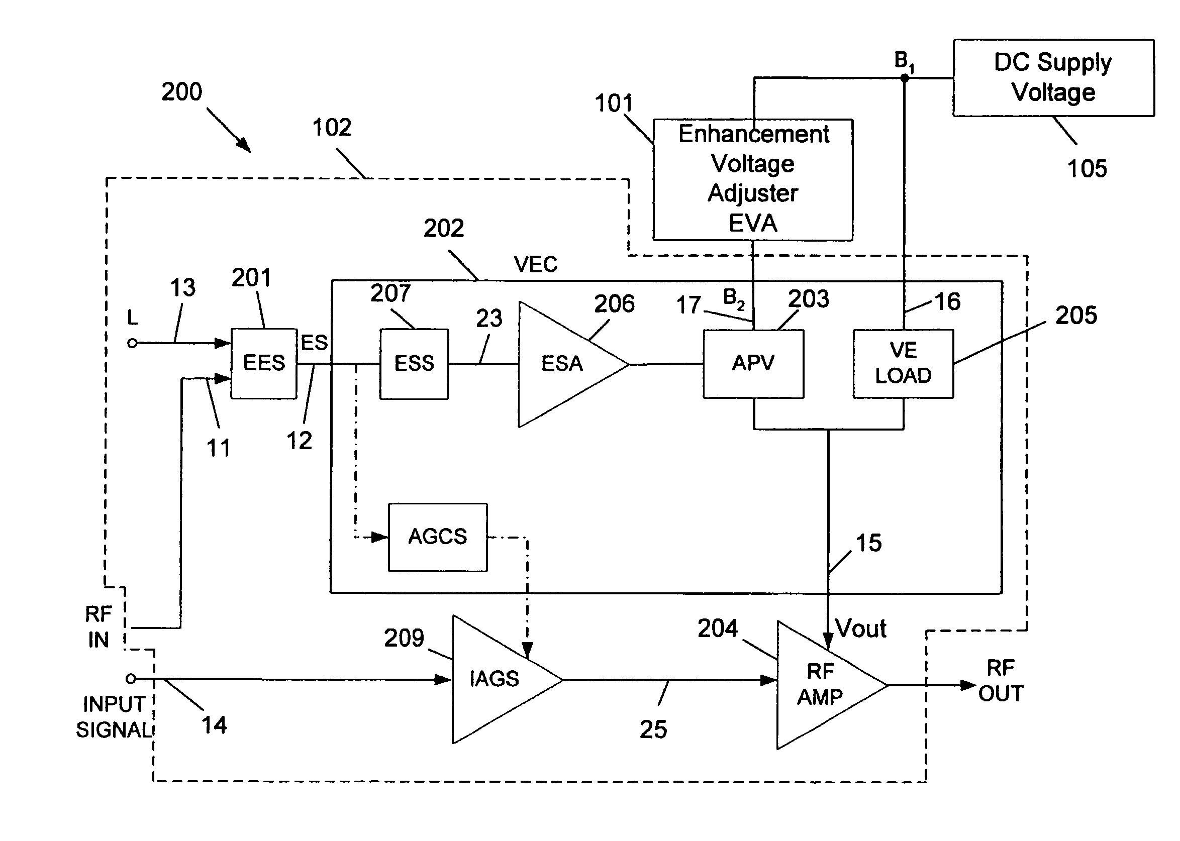
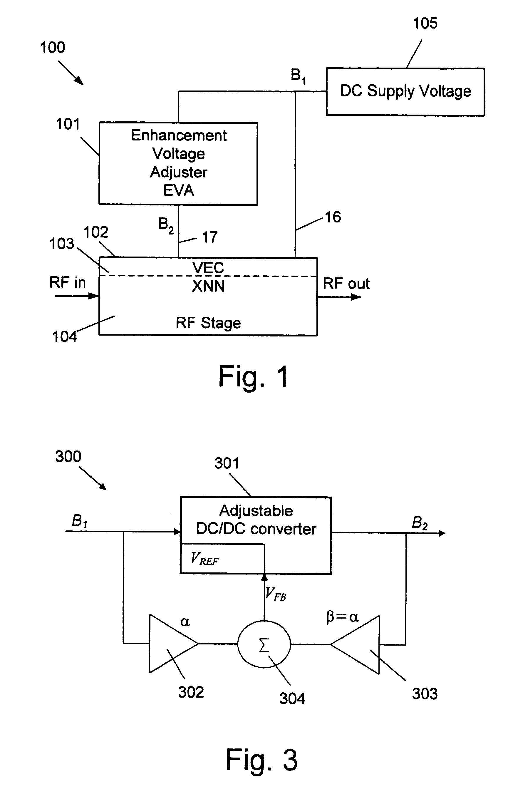
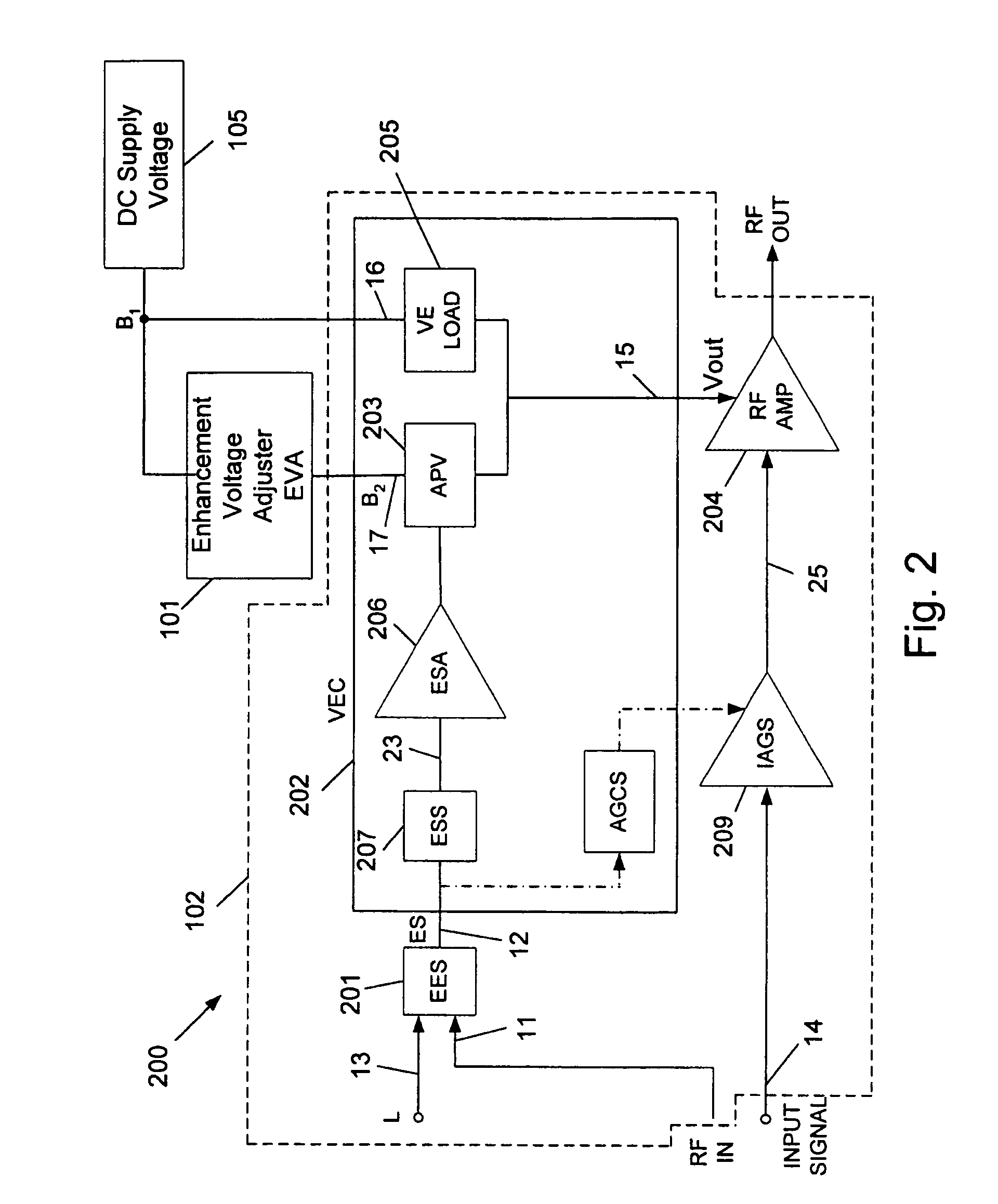
[0032]FIG. 1 is a block diagram of the basic circuit for stabilizing the output power of a power amplifier operated with signals having a large peak-to-average ratio, according to a preferred embodiment of the invention. The circuit 100 comprises an Enhancement Voltage Adjuster (EVA) 101 and an XNN power amplifier 102, consisting of an embedded Voltage Enhancement Circuitry (VEC) 103 and an RF stage 104. The structure of XNN power amplifier 102, as well as it mode of operation during the time periods when the input signal exceeds a predetermined threshold (hereinafter called the “peak time”), are described in details in WO 01 / 67598 (FIG. 2A). Basically, XNN power amplifier 102 comprises two paths for feeding DC voltages. A first DC supply path 16 for constantly providing DC power, a second supply path 17 for providing enhancement supply voltage, exploited during the peak time. These supply paths are shown also in FIG. 2.

[0033]Circuit 100 is fed from a DC power supply 105, the supply...


PUM


Abstract

Method and circuit for stabilizing the output power of a power amplifier, operated with signals having a large peak-to-average ratio and fed by a DC power supply with fluctuating output voltage. An allowable fluctuating range for the voltage output from the DC power supply and a constant voltage level are determined. A controllable voltage enhancement circuitry that can output an enhancement voltage is provided. The input of the voltage enhancement circuitry and a first DC supply path are connected to the output of the DC power supply. The output of the voltage enhancement circuitry is connected to a second DC supply path. While the instantaneous value of the fluctuating output voltage is lower than the constant voltage level, the voltage enhancement circuitry generates an enhancement voltage that causes the sum of the voltages supplied through the first and the second supply paths, to be identical to the constant voltage level.

Description

FIELD OF THE INVENTION[0001]This application claims priority from Israeli Patent Application No. 155581 filed on Apr. 25, 2003, which is incorporated herein by reference. The present invention relates to the field of power amplifiers. More particularly, the invention relates to a method and apparatus for providing a stable power output to power amplifiers, operated with signals having a large peak-to-average ratio under unstable supply voltage conditions, while eliminating the need for DC input voltage stabilization.BACKGROUND OF THE INVENTION[0002]Modem communication systems, such as cellular systems, employ power amplifiers in their basestations, in order to communicate with subscribers that are distributed in cells. These power amplifiers are required to amplify Radio Frequency (RF) signals, such as signals used in communication systems that are required to transmit multiple signals, simultaneously. Multiple signals should be transmitted, for example, due to multiple users sharin...

Claims


Application Information

Patent Timeline
IPC IPC(8): H03F3/04H03F1/30H03F3/189
CPCH03F1/0222H03F3/189H03F1/30H03F2200/504
Inventor BAR-DAVID, ISRAELELIA, AVNERVEINBLAT, ALEXANDER
Owner QUALCOMM INC
Learn More