Flex circuit shielded optical sensor
a shielded optical sensor and flex circuit technology, applied in the direction of printed circuit non-printed electric components, instruments, applications, etc., can solve problems such as brain damage and death
- Summary
- Abstract
- Description
- Claims
- Application Information
AI Technical Summary
Problems solved by technology
Method used
Image
Examples
Embodiment Construction
Sensor Configuration
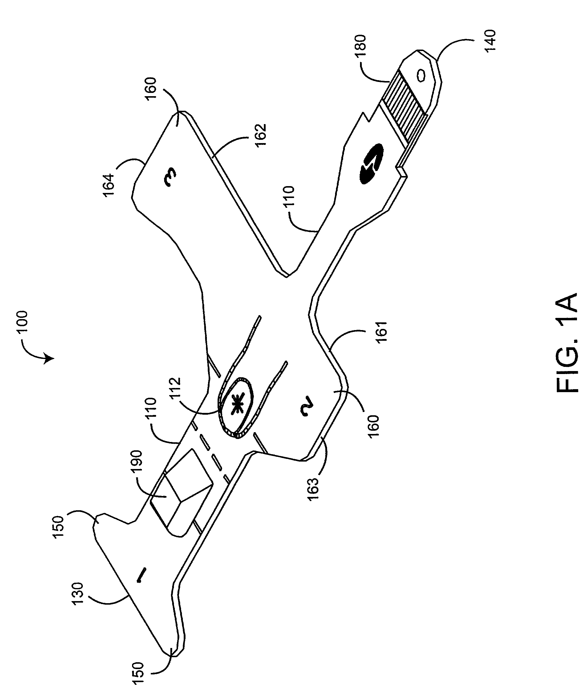
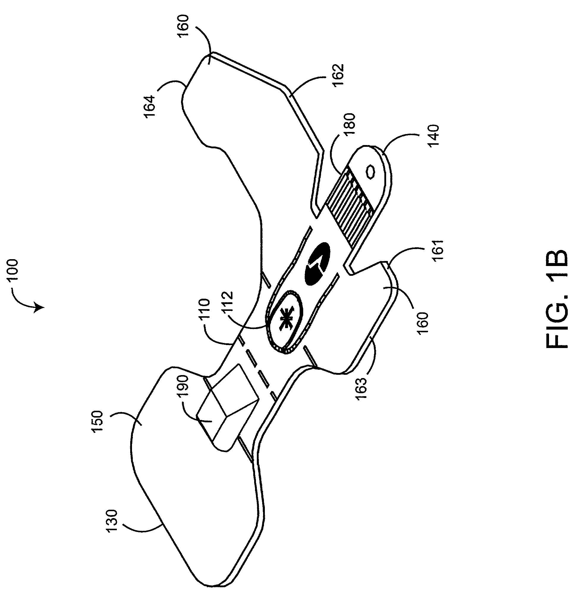
[0019]FIG. 1A illustrates one embodiment of a flex circuit shielded optical sensor. The sensor 100 has a central body 110, a foldover end 130, a connector end 140, a pair of adhesive end attachment wraps 150, a pair of adhesive middle attachment wraps 160, a connector 180 and a detector housing 190. The end wraps 150 and middle wraps 160 extend on either side of the central body 110 and are used to attach the sensor 100 to a patient's finger, in a manner similar to that described in U.S. Pat. No. 5,782,757 entitled “Low Noise Optical Probe,” which is assigned to the assignee of the present invention and incorporated by reference herein. The central body 110 retains a flex circuit assembly 200 (FIGS. 2A–B), described in detail below. The flex circuit assembly 200 is a portion of a sensor core assembly 800 (FIG. 8A–B), which is sandwiched into a completed sensor 100, as described in detail with respect to FIGS. 8–10, below.
[0020]As shown in FIG. 1A, an emitter 760 ...
PUM
| Property | Measurement | Unit |
|---|---|---|
| conductive | aaaaa | aaaaa |
| electromagnetic | aaaaa | aaaaa |
| flexible | aaaaa | aaaaa |
Abstract
Description
Claims
Application Information
 - R&D
- Intellectual Property
- Life Sciences
- Materials
- Tech Scout
- Unparalleled Data Quality
- Higher Quality Content
- 60% Fewer Hallucinations
Browse by: Latest US Patents, China's latest patents, Technical Efficacy Thesaurus, Application Domain, Technology Topic, Popular Technical Reports.
© 2025 PatSnap. All rights reserved.Legal|Privacy policy|Modern Slavery Act Transparency Statement|Sitemap|About US| Contact US: help@patsnap.com


