Method of operating a flamesheet combustor

a combustion system and flame sheet technology, applied in the ignition of turbine/propulsion engines, engine starters, lighting and heating apparatus, etc., can solve the problems of inability to turn down, unstable combustion systems of prior art, and inability to produce acceptable levels of carbon monoxide and oxides of nitrogen

Inactive Publication Date: 2006-01-17
H2 IP UK LTD
View PDF17 Cites 61 Cited by
  • Summary
  • Abstract
  • Description
  • Claims
  • Application Information

AI Technical Summary

Benefits of technology

[0006]The present invention seeks to overcome the shortfalls of the prior art by providing a combustion system that provides stable combustion having low NOx and CO emissions throughout all load conditions. This is accomplished through three dimensional fuel staging, including axial, radial, and circumferential staging such that fuel flow, mixing characteristics, and injection location are precisely controlled depending on the combustor requirements.

Problems solved by technology

Combustion systems of the prior art have been known to become unstable at lower load settings while also producing unacceptable levels of carbon monoxide and oxides of nitrogen at lower load settings, especially below 50% load.
While this staging method and combustor configuration is an enhancement, it is still limited in turndown capability, such that in order to achieve turndown to low part-load settings, the combustor often reverts to the higher emissions diffusion mode.
The combination of potentially unstable combustion and higher emissions often times prevents engine operators from running engines at lower load settings, forcing the engines to either run at higher settings, thereby burning additional fuel, or shutting down, and thereby losing valuable revenue that could be generated from the part-load demand.
A further problem with shutting down the engine is the additional cycles that are incurred by the engine hardware.
Therefore, incurring additional cycles can reduce hardware life requiring premature repair or replacement at the expense of the engine operator.

Method used


Image

  • Method of operating a flamesheet combustor
  • Method of operating a flamesheet combustor
  • Method of operating a flamesheet combustor

Examples


Embodiment Construction

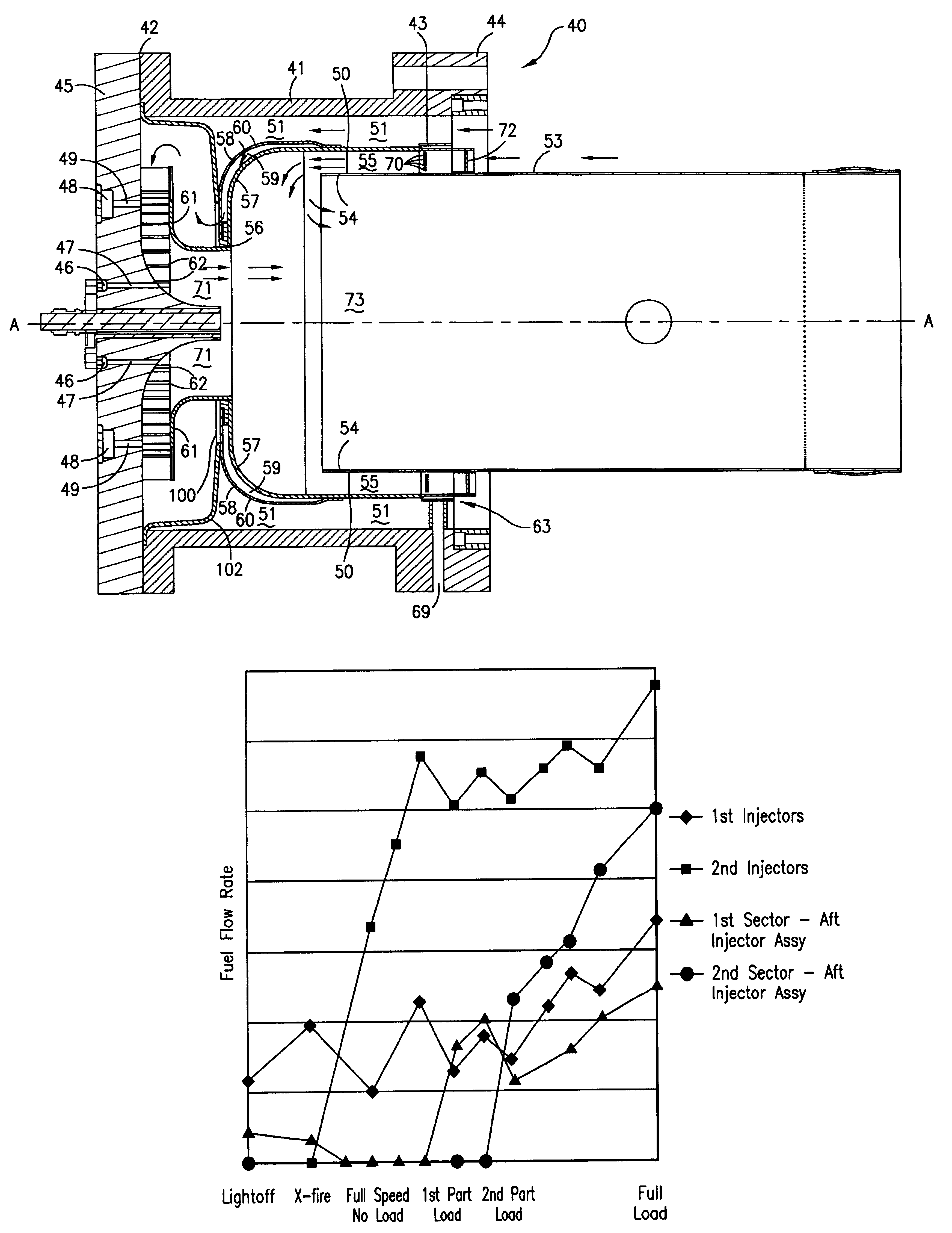
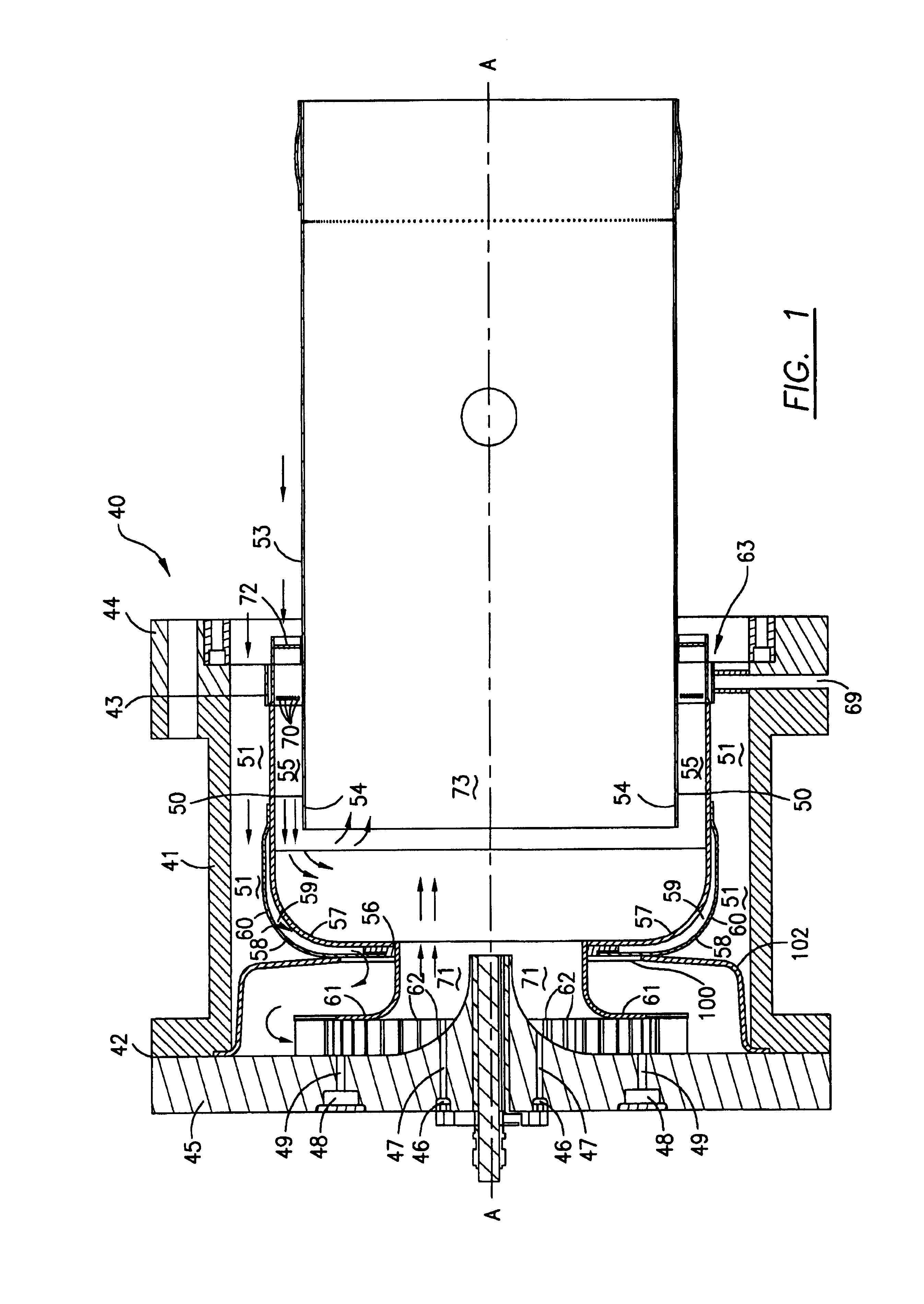
[0016]Referring to FIG. 1, a gas turbine combustion system 40 in accordance with the present invention is shown. A combustion system 40 is provided, including a casing 41 having a first end 42, a second end 43, and a center axis A—A. Casing 41, which is mounted to an engine through flange 44, is in fluid communication with compressed air from a compressor. An end cover 45 is fixed to casing first end 42, with end cover 45 having at least one fuel source in fluid communication with at least one set of injectors. In the preferred embodiment a first fuel source 46 is in fluid communication with a plurality of first injectors 47, where first injectors 47, comprising at least two injectors, are arranged in a first array radially outward of center axis A—A. Furthermore, the preferred embodiment of end cover 45 also contains a second fuel source 48 in fluid communication with a plurality of second injectors 49, where second injectors 49 are arranged in a second array radially outward of fi...


PUM


Abstract

A method of operating a gas turbine combustion system having reduced emissions and improved flame stability at multiple load conditions is disclosed. The improved combustion system accomplishes this through complete premixing, a plurality of fuel injector locations, combustor geometry, and precise three dimensional staging between fuel injectors. Axial, radial, and circumferential fuel staging is utilized including fuel injection proximate air swirlers. Furthermore, strong recirculation zones are established proximate the introduction of fuel and air premixture from different stages to the combustion zone. Fuel injection staging sequences are disclosed that create the conditions necessary to provide stable combustion and reduced emissions at multiple load conditions.

Description

TECHNICAL FIELD[0001]This invention relates in general to gas turbine combustion systems and specifically to a method of operating a gas turbine combustion system at significantly lower load conditions while having stable combustion and lower emissions.BACKGROUND[0002]Gas turbine engines typically include a compressor, one or more combustors each having a fuel injection system, and a turbine section. In an engine having a plurality of combustors, they are typically arranged in an annular array about the engine. The compressor pressurizes inlet air, which is then introduced to the combustors, where it is used to cool the combustion chamber as well to provide air for the combustion process. The hot gases resulting from the combustion process are then directed to drive a turbine. For land-based gas turbines whose primary purpose is to generate electricity, a generator is coupled to the turbine shaft such that the turbine drives the generator.[0003]While a full load condition is the mos...

Claims


Application Information

Patent Timeline
Patent Type & Authority Patents(United States)
IPC IPC(8): F02C7/228F02C9/26F23R3/28F23R3/30F23R3/34
CPCF23R3/286F23R3/343F23R2900/00014
Inventor STUTTAFORD, PETER J.JENNINGS, STEPHENCHEN, YAN
Owner H2 IP UK LTD
Why Eureka
Try Eureka