
Reciprocable impact hammer

a hammer and hammer head technology, applied in the direction of driving apparatus, manufacturing tools, metal-working machine components, etc., can solve the problems of coiled or jointed tubing damage, torsional stress that might damage or disconnect the tubing, and it is impossible to rotate the string formed from many thousands of feet of coiled or jointed tubing, so as to achieve efficient torque transmission and avoid excessive wear of the hammer.

Active Publication Date: 2006-01-17
GENERAL MOTORS COMPANY +1
View PDF15 Cites 20 Cited by
  • Summary
  • Abstract
  • Description
  • Claims
  • Application Information

AI Technical Summary

Benefits of technology

The invention is a reciprocal impact hammer for use in a downhole location. It includes a tool support member, a hammer member, a jack mechanism, a connector member, and a transmission. The hammer member and the tool support member are moveably captive one relative to each other and secured to the hammer member. The jack mechanism is reversible to allow for collapsing of the hammer member and the tool support member together. The connector member and the hammer member are moveably captive one relative to each other. The transmission operatively interconnects the connector member and the hammer member and converts linear motion to rotary motion. The hammer member includes a resilient biasing member and a fluted dart. The transmission includes a thrust bearing and a cone clutch. The connector member includes an engagement portion for connecting to a fluid supply line. The technical effects of the invention are efficient and efficient torque transmission without excessive wear of the hammer and a compact design for downhole use.

Problems solved by technology

Conventional drill bits and other rotary tools are not suitable for use with either coiled or jointed tubing.
This is because in use such tools create torsional stresses that might damage or disconnect the tubing.
Also it is impractical to rotate a string formed from many thousands of feet of coiled or jointed tubing.

Method used


Image

  • Reciprocable impact hammer
  • Reciprocable impact hammer
  • Reciprocable impact hammer

Examples


Embodiment Construction

[0001]Background of the Invention

[0002]The invention relates to a reciprocable impact hammer and more particularly to an impact hammer the tool support member of which is rotatable while under load.

[0003]Such a hammer is useable in operations aimed at creating, enlarging or otherwise working on a borehole.

[0004]Most commonly the need to carry out such operations arises in the oil and gas industries. In these industries it is very common to sink many boreholes, for purposes including but not limited to:[0005]geological and formation fluid sample acquisition;[0006]downhole data logging and / or processing; and[0007]oil and / or gas production.

[0008]Boreholes are also commonly sunk in other industries. Examples include but are not limited to:[0009]the acquisition of subterranean mineral samples in e.g. coal and other mining industries;[0010]downhole data logging in non-hydrocarbon bearing formations such as coal fields; and[0011]the testing and / or productionisation of water wells and aquif...


PUM


Abstract

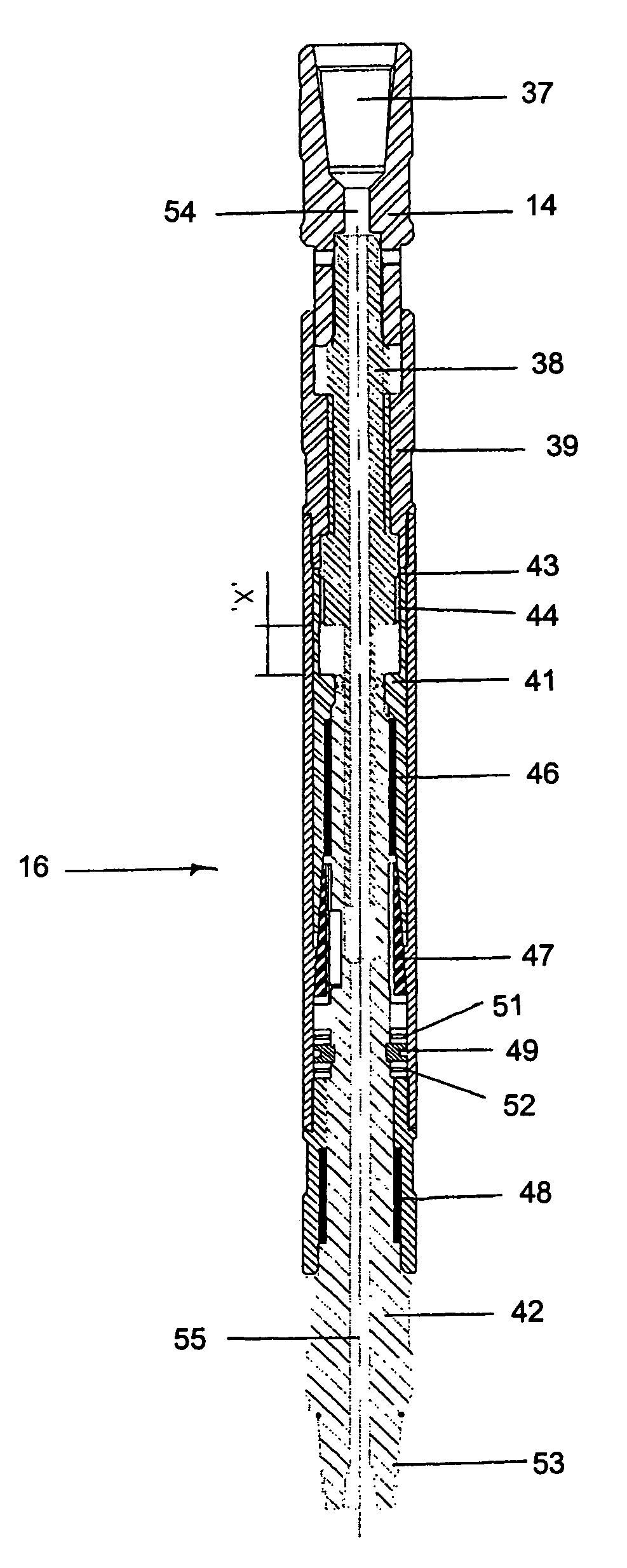
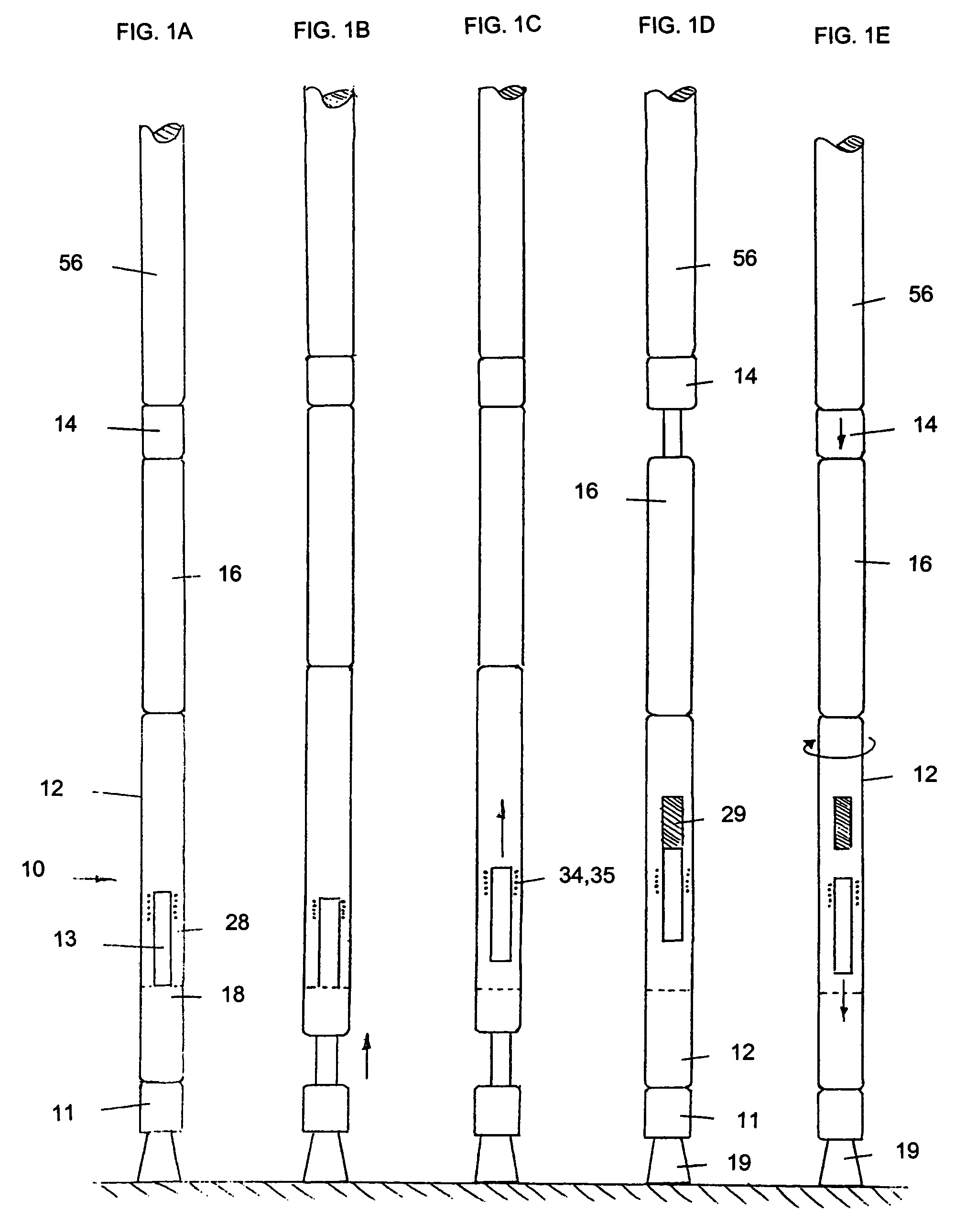
In the field of borehole creation there is a need for a reciprocable impact hammer with a tool that is rotatable while under load. A reciprocable impact hammer (10) for use in a downhole location comprises a tool support member (11); a hammer member (12); a jack mechanism (13); a connector member (14); and a transmission (16). The transmission (16) converts linear motion of the connector member (14) to rotary motion of the hammer member (12) whereby when a force acts on the connector member (14) via the hammer member (12) and the tool support member (11) operation of the jack mechanism (13) causes initial elongation of the impact hammer (10) followed in succession by:(i) collapsing of the hammer member (12) and the tool support member (11) together such that the hammer member (12) separates from the connector member (14) and imparts an impulse to the tool support member (11); and(ii) movement of the connector member (14) towards the hammer member (12) under the influence of the force whereby the transmission (16) causes rotation of the remainder of the impact hammer (10).

Description

DESCRIPTION OF THE INVENTION[0001]Background of the Invention[0002]The invention relates to a reciprocable impact hammer and more particularly to an impact hammer the tool support member of which is rotatable while under load.[0003]Such a hammer is useable in operations aimed at creating, enlarging or otherwise working on a borehole.[0004]Most commonly the need to carry out such operations arises in the oil and gas industries. In these industries it is very common to sink many boreholes, for purposes including but not limited to:[0005]geological and formation fluid sample acquisition;[0006]downhole data logging and / or processing; and[0007]oil and / or gas production.[0008]Boreholes are also commonly sunk in other industries. Examples include but are not limited to:[0009]the acquisition of subterranean mineral samples in e.g. coal and other mining industries;[0010]downhole data logging in non-hydrocarbon bearing formations such as coal fields; and[0011]the testing and / or productionisat...

Claims


Application Information

Patent Timeline
Patent Type & Authority Patents(United States)
IPC IPC(8): B23Q5/027E21B4/16
CPCE21B4/16
Inventor MARSH, BRENT
Owner GENERAL MOTORS COMPANY
Learn More