Control module for an injector of an accumulator injection system

a technology of control module and injector, which is applied in the direction of fluid pressure injection control, fuel injection apparatus, charge feed system, etc., can solve the problems of appreciable efficiency loss, achieve the effect of improving the injection accuracy and the construction of the injector, and improving the accuracy of the injector

Inactive Publication Date: 2006-01-17
SIEMENS AG
View PDF16 Cites 15 Cited by
  • Summary
  • Abstract
  • Description
  • Claims
  • Application Information

AI Technical Summary

Benefits of technology

[0019]In order further to improve the accuracy of the injector during the injection of fuel, one or more centering surfaces are provided on the guide device, in order to center the valve body. A high accuracy of movement of the valve body can thereby be ensured.
[0020]The injection accuracy and the construction of the injector can be further improved in that, preferably, the control piston and the valve body are designed as a common component. Particularly preferably, the valve body is in this case designed as a nozzle needle.
[0021]The control module according to the invention for an injector is preferably used in accumulator injection systems, such as, for example, common-rail injectors for diesel engines. Since the control module according to the invention combi

Problems solved by technology

However, this permanent leakage caus

Method used


Image

  • Control module for an injector of an accumulator injection system
  • Control module for an injector of an accumulator injection system
  • Control module for an injector of an accumulator injection system

Examples


Embodiment Construction

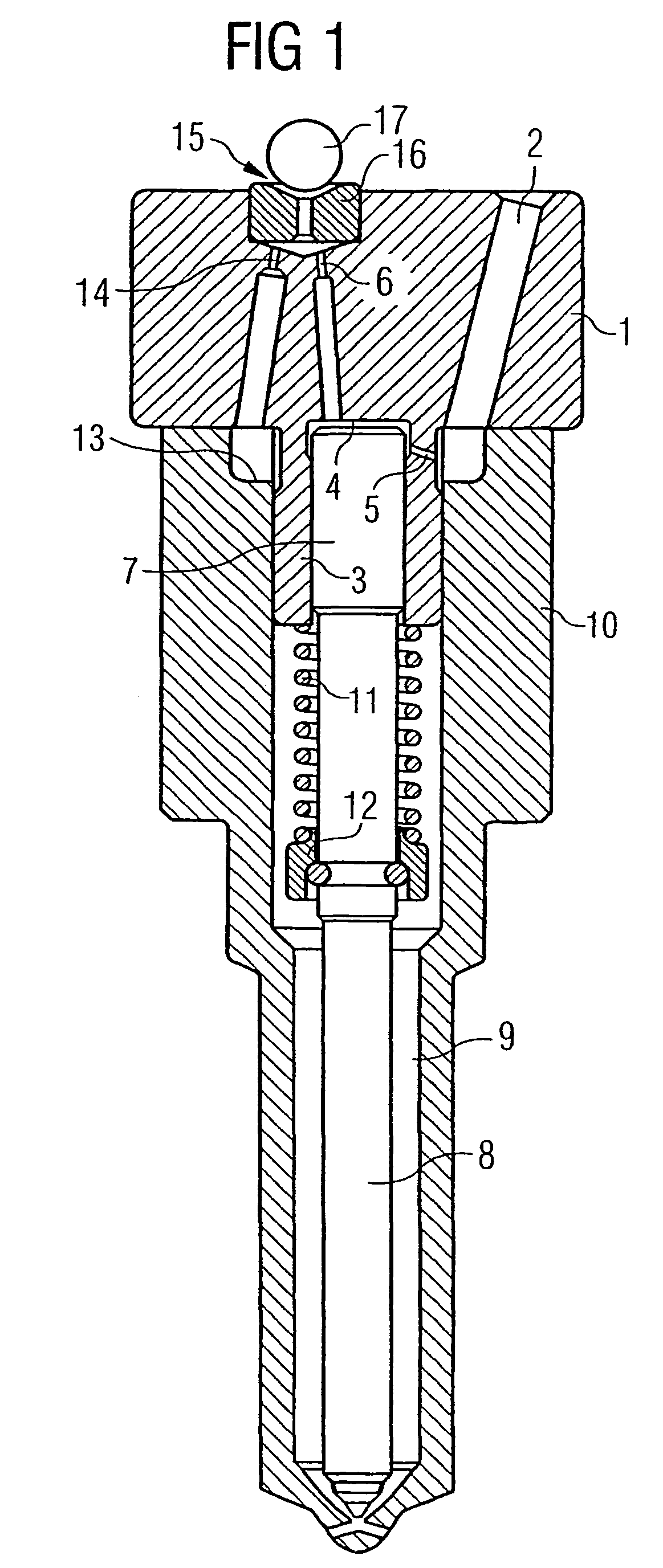
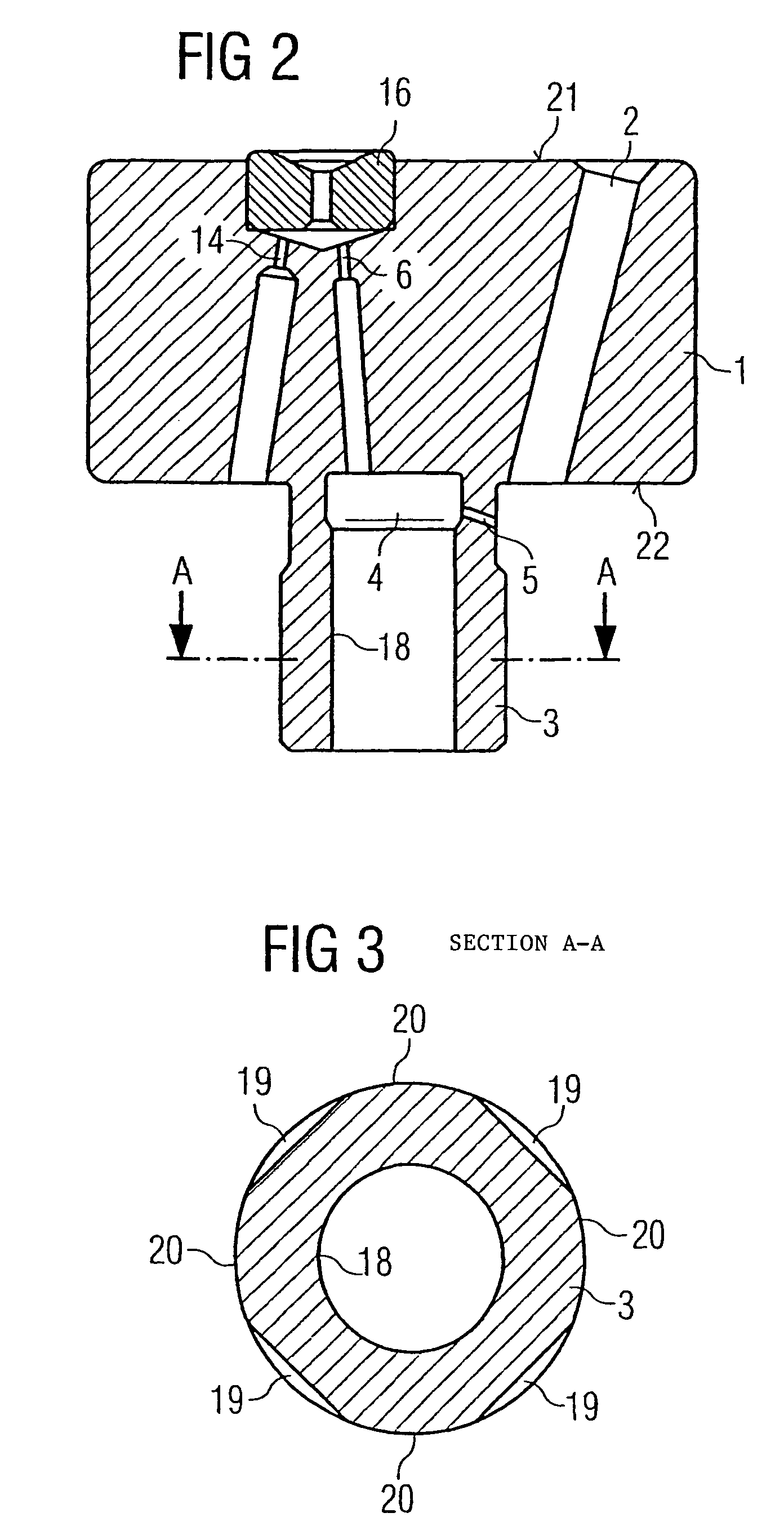
[0028]An exemplary embodiment according to the present invention is described below with reference to FIG. 1 to 3.

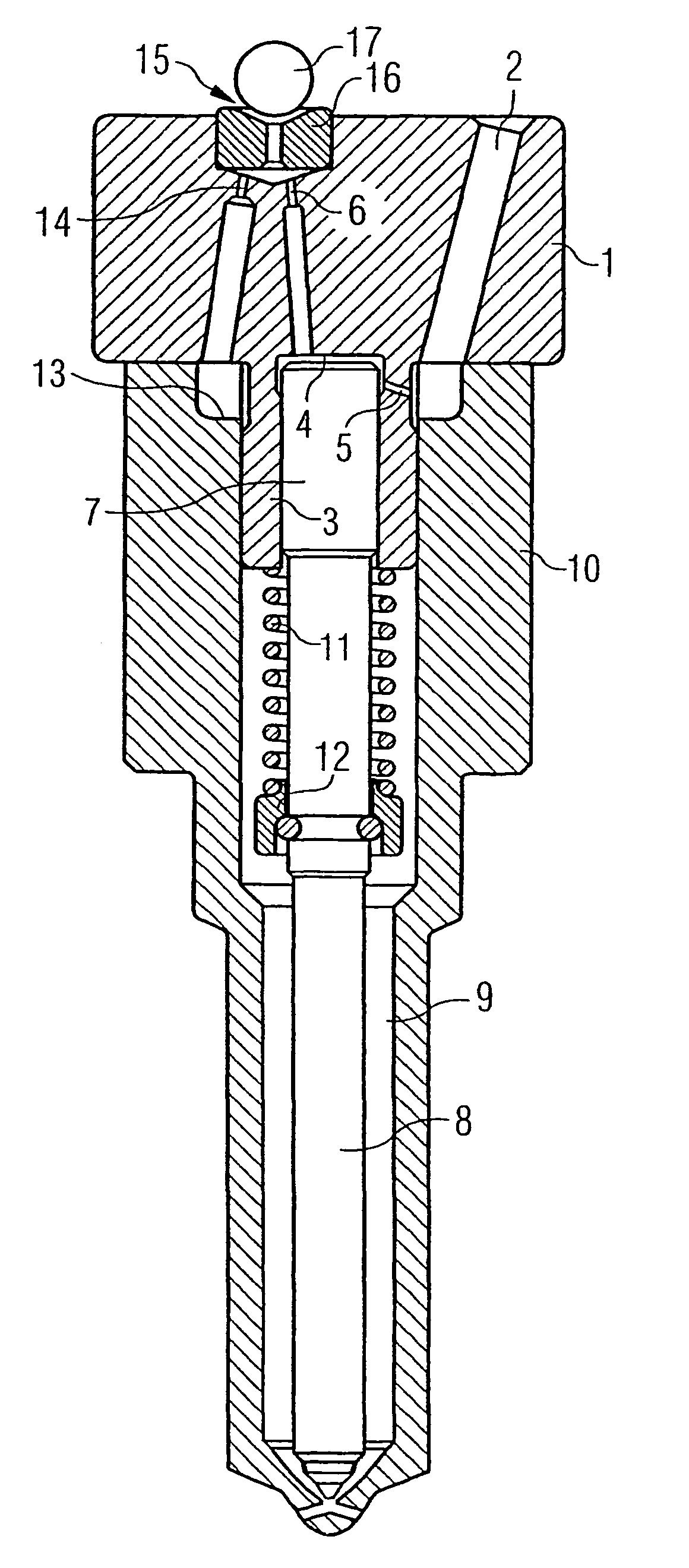
[0029]As shown particularly in FIG. 1, the control module 1 according to the invention for an injector of an accumulator injection system has a highly compact construction. The control module 1 comprises a high-pressure inflow 2, in order to deliver fuel from a high-pressure pump to the injector. The control module 1 further comprises a guide device 3 for guiding a valve body 8 of the injector, a control space 4, an inflow throttle 5 and an outflow throttle 6. The inflow throttle 5 makes a connection between the high-pressure inflow 2 and the control space 4. The outflow throttle 6 connects the control space 4 to a control valve 15. The control valve 15 comprises a valve seat 16 and a valve ball 17 and is lifted off from the valve seat 16 by means of an actuator (not shown), such as, for example, a piezoelectric actuator, a magnetostrictive actuator or a solenoid, and in...


PUM


Abstract

A control module (1) for an injector of an accumulator injection system is used to control and guide a valve body (8). The control module comprises a high pressure supply line (2) for supplying fuel, and a guiding device (3) for guiding the valve body (8). A control room (4), an inlet throttle (5) and an outlet throttle (6) are also provided. The inlet throttle (5) connects the high pressure supply line (2) to the control chamber (4) and the outlet throttle (6) connects the control chamber (4) to a control valve (15). A control piston (7) is arranged in the control chamber (4), the end of the control piston opposite the control chamber (4) being connected to a high pressure region (9) on the valve body (8).

Description

CROSS REFERENCE TO RELATED APPLICATION[0001]This application is a continuation of copending International Application No. PCT / DE02 / 02383 filed Jul. 1, 2002 which designates the United States, and claims priority to German application DE 101 31 953.3 filed Jul. 2, 2001.TECHNICAL FIELD[0002]The present invention relates to a control module for an injector of an accumulator injection system for the control and guidance of an injector valve body.BACKGROUND OF THE INVENTION[0003]Injectors for accumulator injection systems are known in various embodiments. A known injector of this type is illustrated by way of example in FIG. 4. Here, fuel is delivered into the surrounding region of the nozzle needle 36 via a high-pressure feed line 30. The nozzle needle 36 is in contact with a control piston 31 which is arranged with one end in a control space 32. The pressure in the control space 32 can be controlled in a known way via a control valve 33, so that the control space 32 can be connected to...

Claims


Application Information

Patent Timeline
IPC IPC(8): F02M59/00F02M47/00F02M61/10F02M47/02F02M61/16F02M61/20F02M63/00
CPCF02M47/02F02M47/027F02M61/168F02M2547/003F02M61/1866F02M2200/21
Inventor BLOCHING, WOLFGANGSCHURZ, WILLIBALD
Owner SIEMENS AG
Why Eureka
Try Eureka