
Micropump with integrated pressure sensor

Active Publication Date: 2006-01-17
WATERS TECH CORP
View PDF8 Cites 27 Cited by
  • Summary
  • Abstract
  • Description
  • Claims
  • Application Information

AI Technical Summary

Benefits of technology

[0006]One representative advantage of the present invention would allow for improved process control and manufacturing of integrated micropump systems at substantially lower cost. Additional advantages of the present invention will be set forth in the Detailed Description which follows and may be obvious from the Detailed Description or may be learned by practice of exemplary embodiments of the invention. Still other advantages of the invention may be realized by means of any of the instrumentalities, methods or combinations particularly pointed out in the claims.

Problems solved by technology

Conventional pumps and pumping designs have been used in several applications; however, many of these are generally too cumbersome and complex for application with microfluidic systems.
Consequently, conventional designs have generally not been regarded as suitable for integration with portable ceramic technologies or in various applications requiring, for example, reduced form factor, weight or other desired performance and / or fabrication process metrics.
Moreover, previous attempts with integrating microfluidic pumps in laminated substrates have met with considerable difficulties in producing reliable fluidic connections and / or hermetic seals capable of withstanding manufacturing processes and / or operational stress while maintaining or otherwise reducing production costs.

Method used


Image

  • Micropump with integrated pressure sensor
  • Micropump with integrated pressure sensor
  • Micropump with integrated pressure sensor

Examples


Embodiment Construction

[0015]The following descriptions are of exemplary embodiments of the invention and the inventors' conceptions of the best mode and are not intended to limit the scope, applicability or configuration of the invention in any way. Rather, the following description is intended to provide convenient illustrations for implementing various embodiments of the invention. As will become apparent, changes may be made in the function and / or arrangement of any of the elements described in the disclosed exemplary embodiments without departing from the spirit and scope of the invention.

[0016]Various representative implementations of the present invention may be applied to any system and / or method for fluid transport. As used herein, the terms “fluid”, “fluidic” and / or any contextual, variational or combinative referent thereof, are generally intended to include anything that may be regarded as at least being susceptible to characterization as generally referring to a gas, a liquid, a plasma and / or...


PUM


Abstract

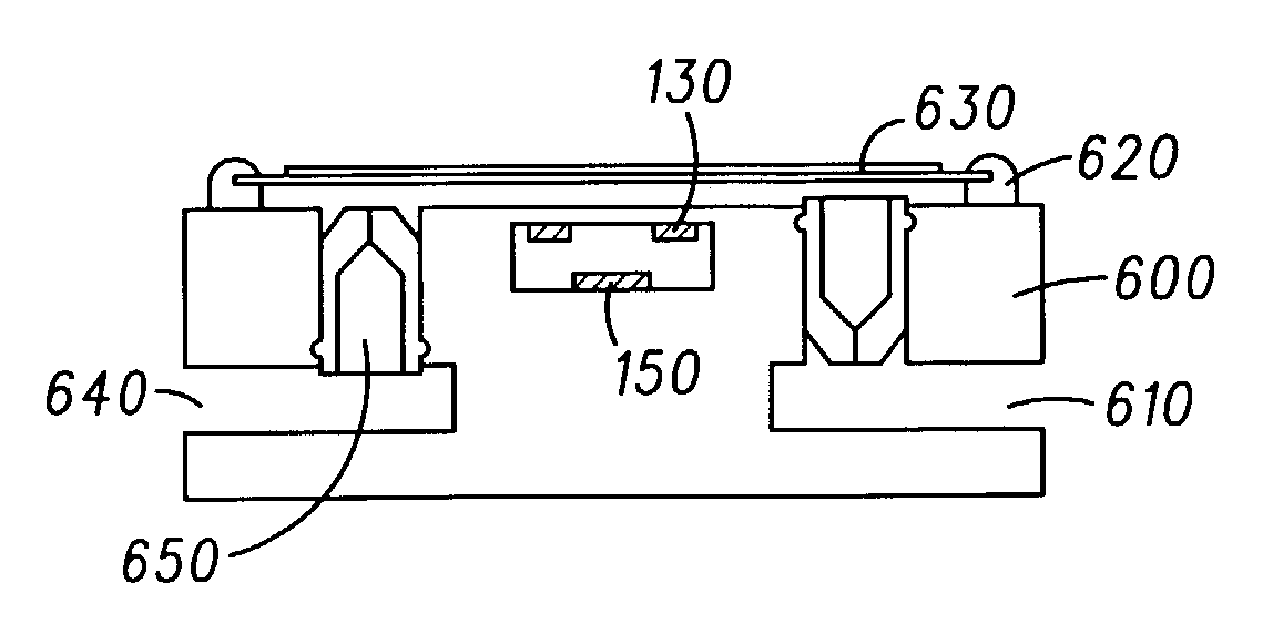
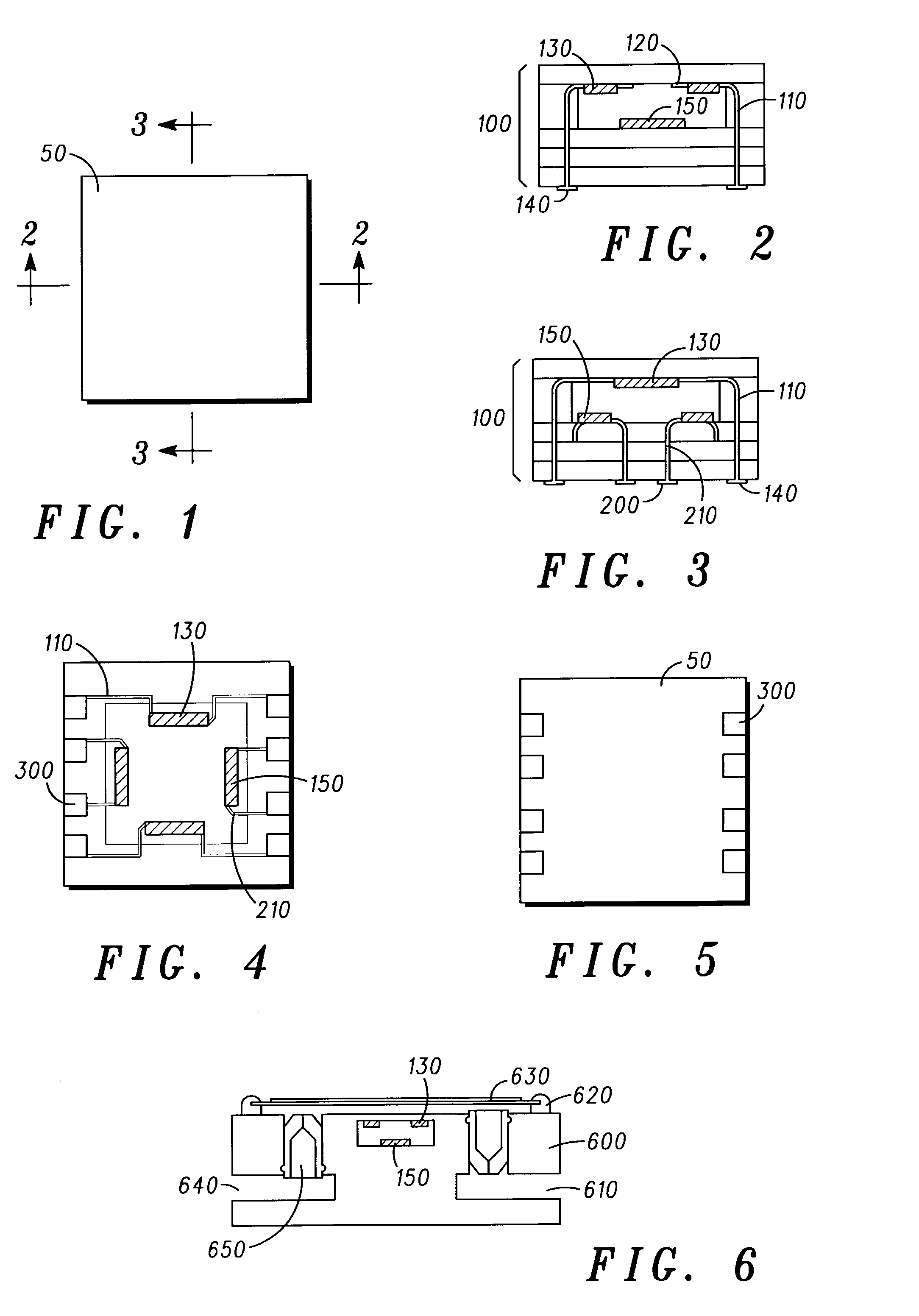
An exemplary system and method for manufacturing micropump systems having integrated piezoresistive sensors is disclosed as including inter alia: a substrate, an inlet channel, an outlet channel, a pumping cavity, a first valve for permitting fluid flow from the inlet channel to the pumping cavity and restricting backflow of purged fluid from the pumping cavity to the inlet channel; a second valve for permitting fluid flow from the pumping cavity to an outlet channel and restricting backflow of purged fluid from the outlet channel to the pumping cavity; a pump actuator element; a pressure sensing cavity surface capable of at least partial mechanical deformation; a plurality of piezoresistors disposed within the sensing cavity; a plurality of contact pads; a plurality of conductive pathways connecting the piezoresistors and the contact pads; and a substantially monolithic device package, wherein the sensing cavity is substantially contained within the micropump device package. Disclosed features and specifications may be variously controlled, adapted or otherwise optionally modified to improve micropump operation in any microfluidic application. Exemplary embodiments of the present invention representatively provide for piezoresistive pressure sensors that may be readily integrated with existing portable ceramic technologies for the improvement of device package form factors, weights and other manufacturing and / or device performance metrics.

Description

FIELD OF INVENTION[0001]The present invention relates to micropumps, and more particularly, in one representative and exemplary embodiment, to multilayer ceramic micropumps having integrated piezoresistive pressure sensors for improved performance, efficiency and fabrication cost savings in microfluidic applications.BACKGROUND[0002]Development of microfluidic technology has generally been driven by parallel ontological advancements in the commercial electronics industry with the ever-increasing demand for sophisticated devices having reduced part counts, weights, form factors and power consumption while improving or otherwise maintaining overall device performance. In particular, advancement of microfluidic technology has met with some success in the areas of packaging and the development of novel architectures directed to achieving many of these aims at relatively low fabrication cost.[0003]The development of microfluidic systems, based on for example, multilayer laminate substrate...

Claims


Application Information

Patent Timeline
IPC IPC(8): F04B43/04F04B15/08
CPCF04B43/043F04B15/08A61M5/14224A61M2205/0294
Inventor DAI, XUNHUXIE, CHENGGANG
Owner WATERS TECH CORP
Learn More