Alignment apparatus and exposure apparatus using the same

a technology of alignment apparatus and exposure apparatus, which is applied in the direction of photomechanical apparatus, process and machine control, instruments, etc., can solve the problems of inability to perform high-accuracy position control, movable element is susceptible to cable disturbance, and the air pressure of the movable element is too high

Inactive Publication Date: 2006-01-17
CANON KK
View PDF39 Cites 77 Cited by
  • Summary
  • Abstract
  • Description
  • Claims
  • Application Information

AI Technical Summary

Problems solved by technology

However, in the conventional arrangement, the movable element levitates by the air pressure and cannot be used in a vacuum.
This makes it impossible to perform high-accuracy position control.
For this reason, the movable element is susceptible to disturbance by the cables.
This also makes it impossible to perform high-accuracy position control.
In addition, the arrangements shown in FIGS. 24 to 26 can generate a thrust only in the first and second directions perpendicular to each other of the in-place direction and cannot perform tilt correction and position control in a rotational direction to control the posture of the stage mechanism.
For this reason, they cannot be used in an apparatus which requires a precise posture and high alignment accuracy, such as a semiconductor exposure apparatus.
This increases the complexity of the stage mechanism.

Method used


Image

  • Alignment apparatus and exposure apparatus using the same
  • Alignment apparatus and exposure apparatus using the same
  • Alignment apparatus and exposure apparatus using the same

Examples


Embodiment Construction

[0045]A preferred embodiment of the present invention will now be described in detail in accordance with the accompanying drawings.

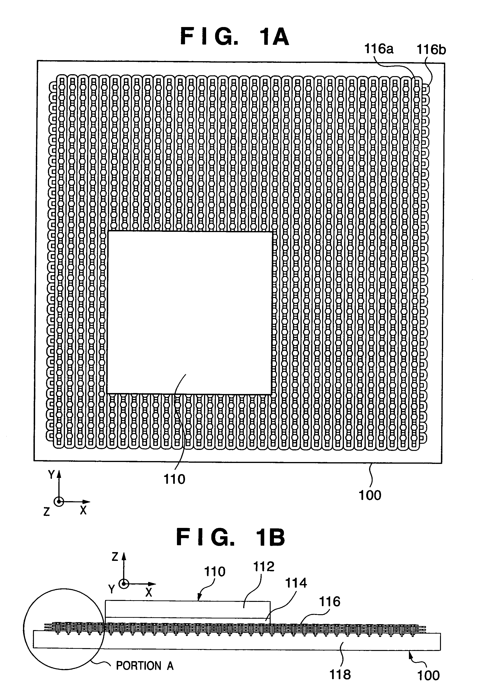
[0046]An embodiment according to the present invention will be described with reference to FIGS. 1A and 1B. FIG. 1A is a view showing a state wherein a movable element 110 is aligned in the X-Y plane of a stator 100. The movable element 110 is implemented as a plate-like member. FIG. 1B is a view showing the relationship between the stator and the movable element as seen in the direction of the X-Z plane. The movable element 110 comprises a top plate 112 almost in the shape of a rectangular parallelepiped and a plurality of permanent magnet arrays 114 arranged below the top plate. The top plate 112 is desirably made of a substance having high specific rigidity such as ceramic.

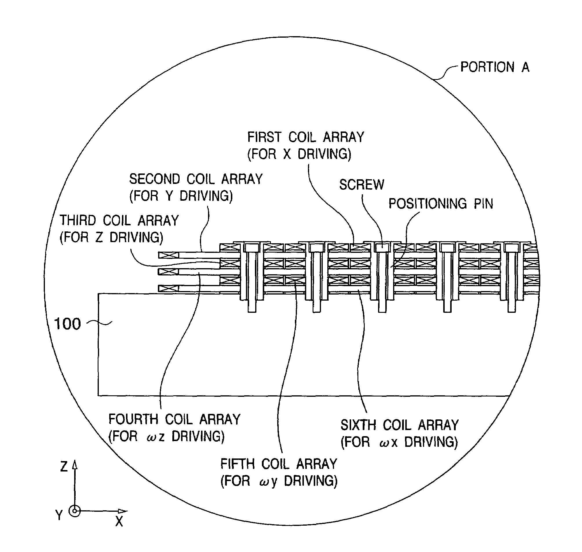
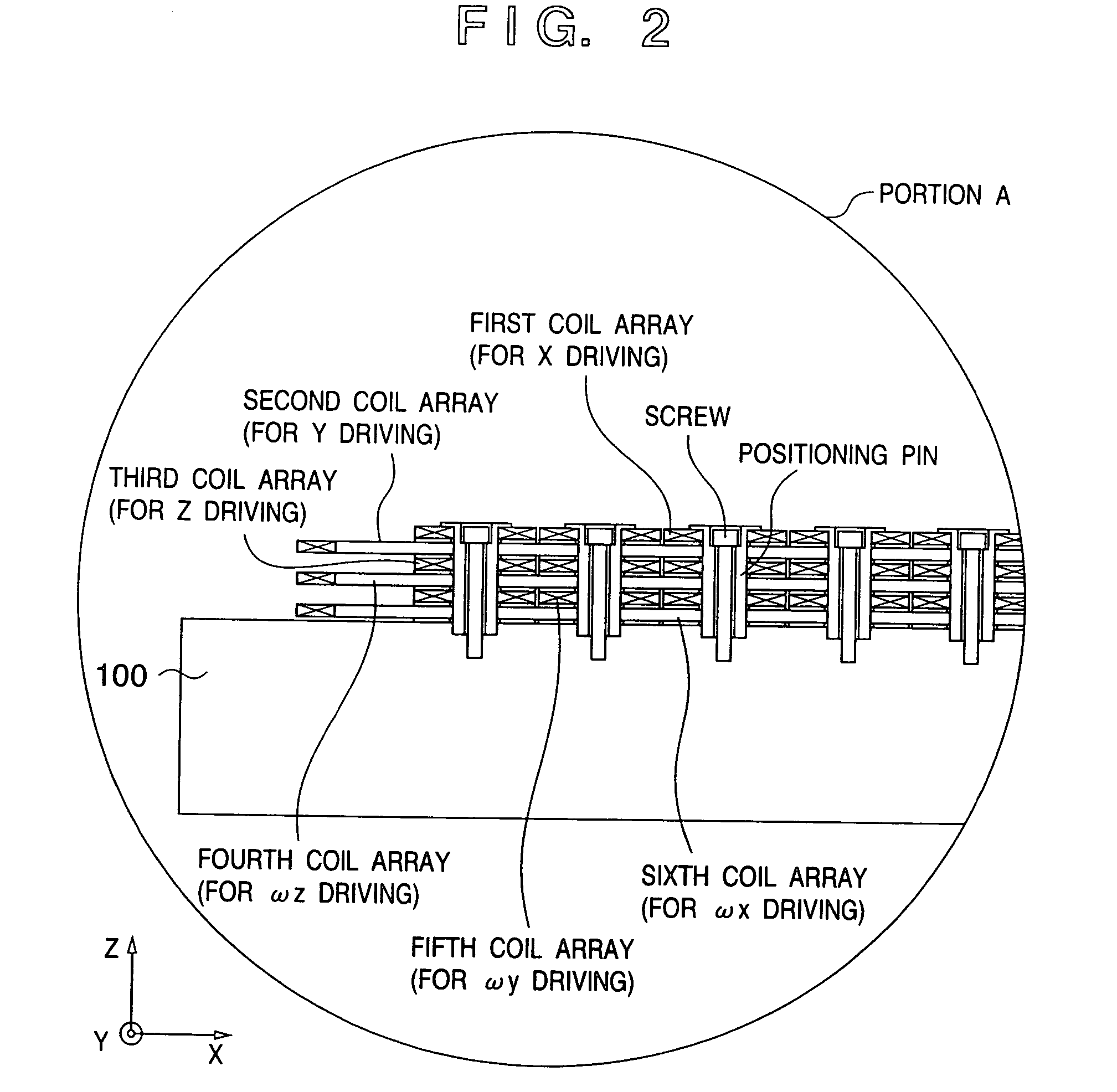
[0047]The stator 100 comprises a base 118 and six layers of coils 116 fixed on the base. Each layer constituting the six layers of coils 116 comprises a plurality of almost oblong c...


PUM

PropertyMeasurementUnit
angleaaaaaaaaaa
angleaaaaaaaaaa
angleaaaaaaaaaa

Abstract

An alignment apparatus which generates a driving force between a plate-like movable element and a stator facing the movable element to control alignment of the movable element includes movable element magnets which are arrayed in a plate-like plane of the movable element in accordance with an array cycle and are magnetized in predetermined directions, stator coils which are arrayed at intervals corresponding to the array cycle, and a current controller which supplies control currents having phase differences to each pair of adjacent ones of the stator coils to generate a driving force for driving the movable element between the movable element magnets and the stator coils facing the movable element magnets. The stator coils, formed by stacking three pairs of the first and second layers, generate translational driving forces with three degrees of freedom and rotational driving forces with three degrees of freedom between the movable element magnets and the stator coils of each layer facing the movable element magnets on the basis of the control currents.

Description

FIELD OF THE INVENTION[0001]The present invention relates to an alignment apparatus capable of high-accuracy alignment and an exposure apparatus using the same.BACKGROUND OF THE INVENTION[0002]A conventional example of a stage mechanism which has a plate-like member as a movable portion to align the movable portion at a predetermined position in an in-place direction is disclosed in a patent publication (Japanese Patent Laid-Open No. 8-006642). In the disclosed arrangement, only a plate-like member which holds a workpiece is two-dimensionally moved using a plane pulse motor as a driving source. This method moves only the plate-like member as the movable portion and thus is suitable for reducing the size and weight of a stage movable portion.[0003]FIG. 24 is a view showing the arrangement of a movable element in a conventional stage mechanism. An air supply hole 60 and units 52, 54, 56 and 58 each having coil-wounded inductor toothed cores are formed in a box-like member 22 to consti...

Claims


Application Information

Patent Timeline
Patent Type & Authority Patents(United States)
IPC IPC(8): H02K41/00G03F7/20G03F9/00G05D3/00H01L21/027H02K9/19H02K9/22H02K16/02H02K41/02H02K41/03H02N15/02H02P25/06
CPCG03F7/70758H02N15/02H02K41/031H02K9/19H02K16/00H02K2201/18H02K16/02H02K9/197
Inventor KORENAGA, NOBUSHIGE
Owner CANON KK
Why Eureka
Try Eureka