Piezoelectric resonator component

a piezoelectric resonator and component technology, applied in piezoelectric/electrostrictive/magnetostrictive devices, piezoelectric/electrostrictive/magnetostrictive devices, piezoelectric/electrostrictive/magnetostriction machines, etc., can solve the problems of increasing manufacturing steps, difficulty in implementing a low-profile design in piezoelectric resonator components, etc., to reduce manufacturing costs, effect effective and reliably

Active Publication Date: 2006-01-17
MURATA MFG CO LTD
View PDF4 Cites 23 Cited by
  • Summary
  • Abstract
  • Description
  • Claims
  • Application Information

AI Technical Summary

Benefits of technology

[0011]To overcome the problems described above, preferred embodiments of the present invention provide a piezoelectric resonator component that eliminates the need for providing additional members such as a paint film and a damping member, simplifies manufact

Problems solved by technology

In this technique, however, the paint films 105 and 106 must be applied, thereby increasing manufacturing steps and leading to a cost increase.
The paint films 105 and 106 cause, due to the thickness thereof, difficulty in implementing a low-profile design in the piezoelectric resonator component.
T

Method used


Image

  • Piezoelectric resonator component
  • Piezoelectric resonator component
  • Piezoelectric resonator component

Examples


Embodiment Construction

[0033]Referring to the drawings, preferred embodiments of the present invention will now be described.

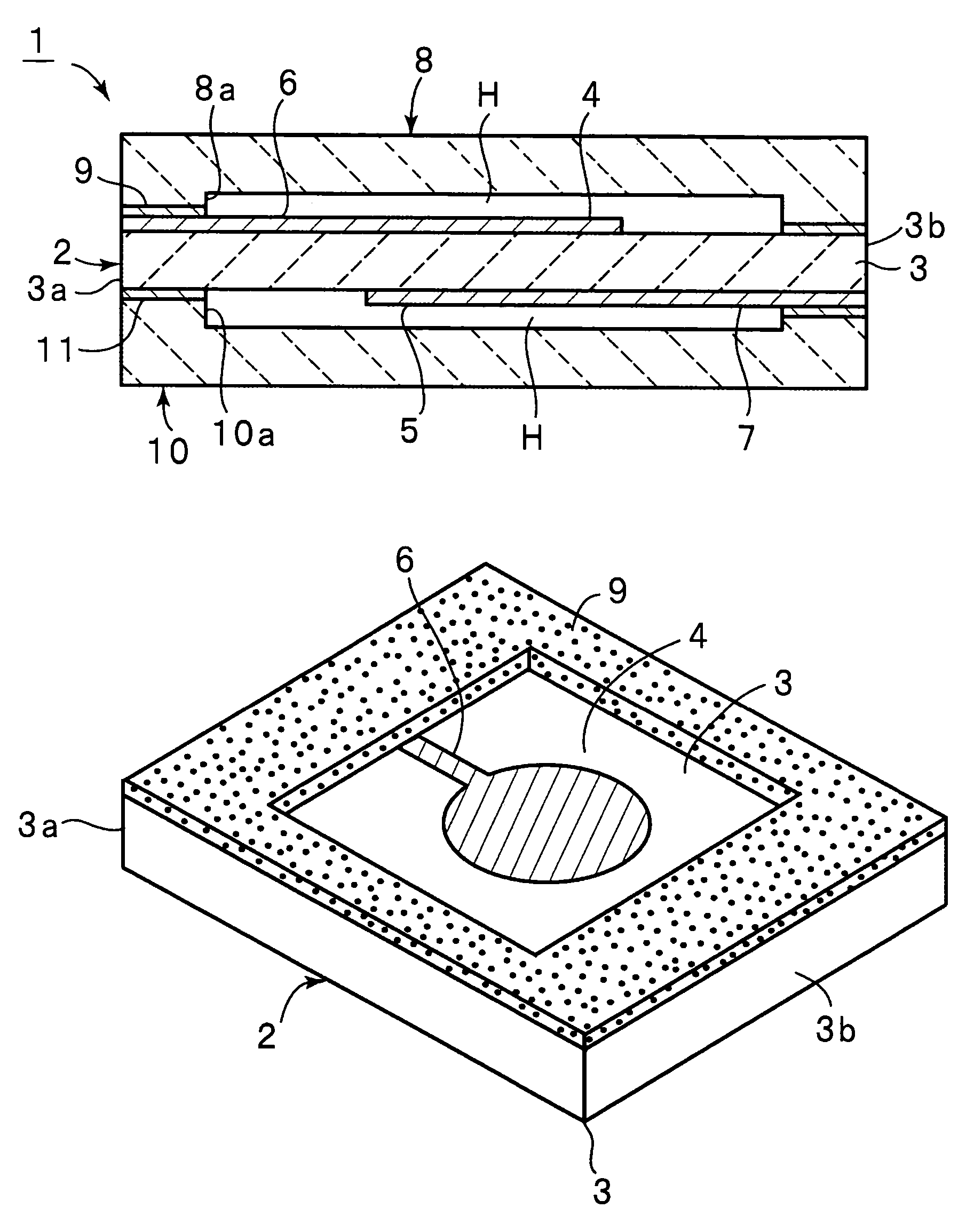
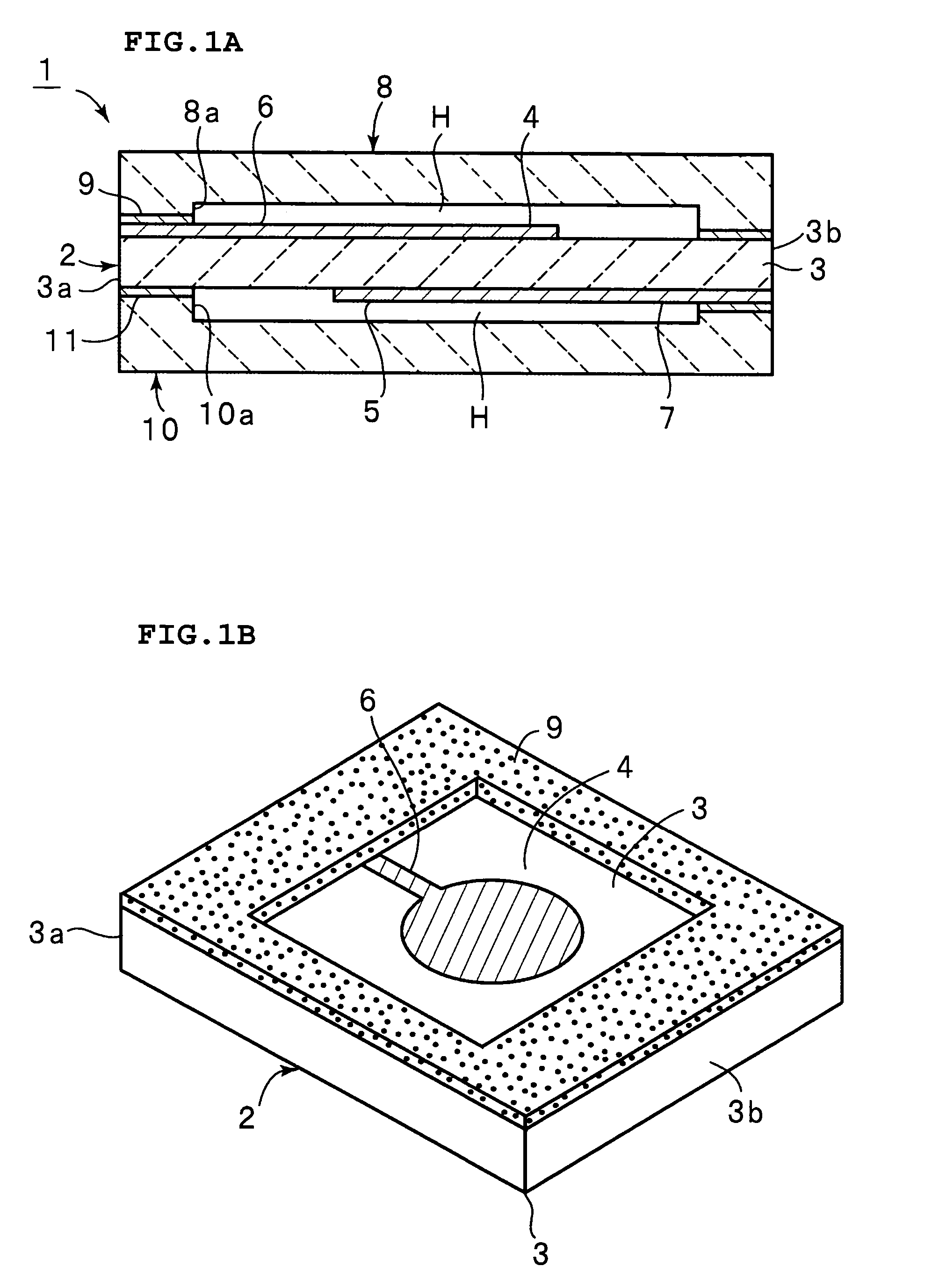
[0034]FIG. 1A is a longitudinal section of a piezoelectric resonator component 1 in accordance with a first preferred embodiment of the present invention and FIG. 1B is a perspective view of a major portion of the piezoelectric resonator component.

[0035]The piezoelectric resonator component 1 includes an energy-trapped piezoelectric resonator 2. The piezoelectric resonator 2 includes a piezoelectric substrate 3 having a substantially rectangular planar shape. The piezoelectric substrate 3, made of a piezoelectric ceramic, such as a lead zirconate titanate ceramic or a lead titanate ceramic, is polarized in the direction of thickness thereof.

[0036]A first vibrating electrode 4 having a substantially circular planar shape is disposed at the approximate center of the top surface of the piezoelectric substrate 3. A second vibrating electrode 5 is disposed on the bottom surface of the pi...


PUM


Abstract

A piezoelectric resonator component includes an energy-trapped piezoelectric resonator utilizing a third order harmonic wave of thickness longitudinal vibration and including a piezoelectric substrate having first and second major surfaces and polarized in a direction of thickness between the first and second major surfaces, and first and second vibrating electrodes opposed to each other with the piezoelectric substrate interposed therebetween, and first and second casing substrates respectively laminated on the first and second major surfaces of the piezoelectric resonator so that cavities are arranged so as not to interfere with vibration of a vibration section where the first and second vibrating electrodes face each other through the piezoelectric substrate. The first and second vibrating electrodes are dimensioned so that the difference between the peak values of the phases of S0 and S1 modes of the fundamental wave of the thickness longitudinal vibration falls within a range of about ±5 degrees.

Description

BACKGROUND OF THE INVENTION[0001]1. Field of the Invention[0002]The present invention relates to energy-trapped piezoelectric resonator components and, in particular, to an energy-trapped piezoelectric resonator component that suppresses a fundamental wave of thickness longitudinal vibration functioning as a spurious wave.[0003]2. Description of the Related Art[0004]Energy-trapped piezoelectric resonators are in widespread use as oscillators. A variety of vibration modes are selectively used depending upon a target frequency.[0005]Japanese Unexamined Patent Application Publication No. 8-148967 discloses an energy-trapped piezoelectric resonator 101 using the fundamental wave of thickness longitudinal vibration. As shown in a perspective view in FIG. 9, the known energy-trapped piezoelectric resonator 101 includes a piezoelectric substrate 102 having a rectangular planar shape. The piezoelectric substrate 102 is made of a piezoelectric ceramic that is polarized in the direction of th...

Claims


Application Information

Patent Timeline
IPC IPC(8): H03H9/19H03H9/17H01L41/08H03H3/02H03H9/02H03H9/10H03H9/13H03H9/15
CPCH03H9/0207H03H9/02157H03H9/177H03H9/132H03H9/1035
Inventor YOSHIO, MASAKAZUKOTANI, KENICHIYAMADA, MITSUHIRO
Owner MURATA MFG CO LTD
Why Eureka
Try Eureka