Stacked OLED display having improved efficiency

a technology of oled display and efficiency, applied in the field of oled color display, can solve the problems of reducing the life or reducing the resolution compared to a prior art three, reducing the efficiency of pixels in the display, and imai design not providing increased power efficiency for emissive full color display

Active Publication Date: 2006-01-17
GLOBAL OLED TECH
View PDF9 Cites 179 Cited by
  • Summary
  • Abstract
  • Description
  • Claims
  • Application Information

AI Technical Summary

Problems solved by technology

Therefore, the design of Siwinski will result in either reduced lifetime or reduced resolution compared to a prior art three element design.
However, such stacked struct

Method used


Image

  • Stacked OLED display having improved efficiency
  • Stacked OLED display having improved efficiency
  • Stacked OLED display having improved efficiency

Examples


Embodiment Construction

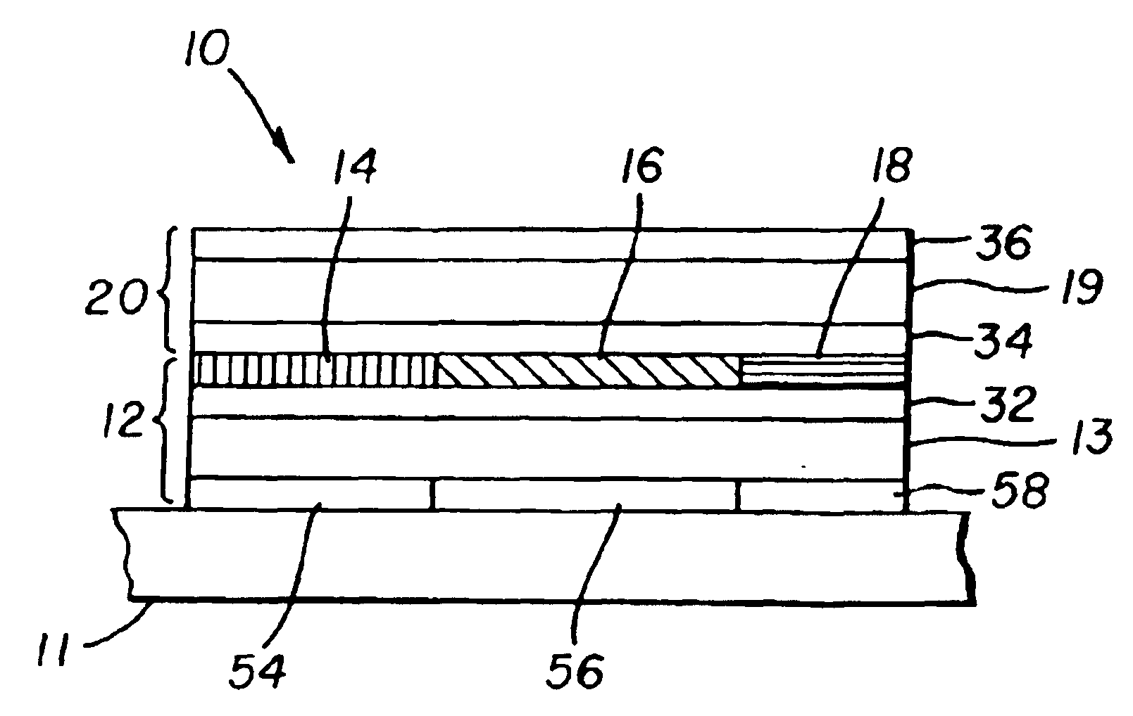
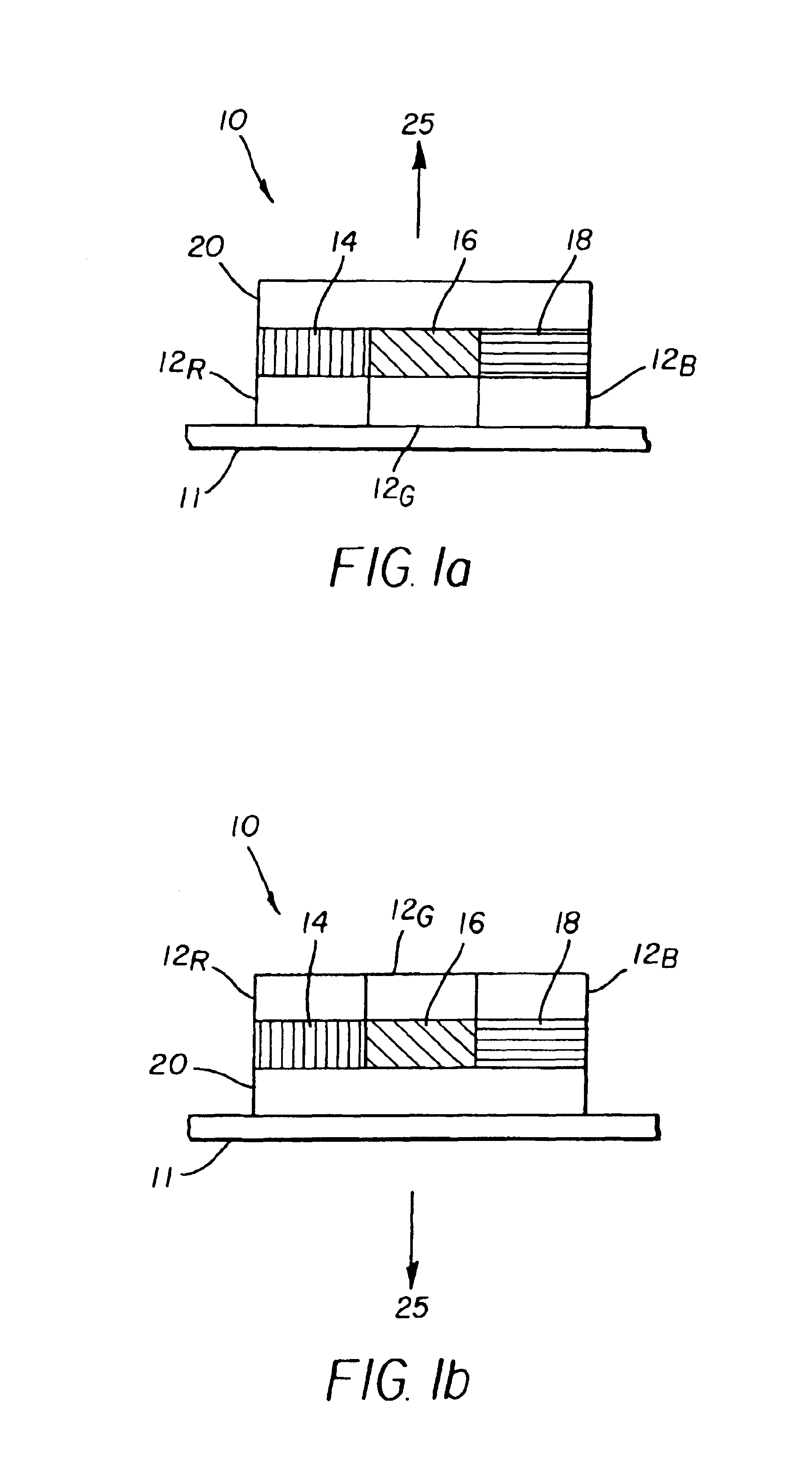
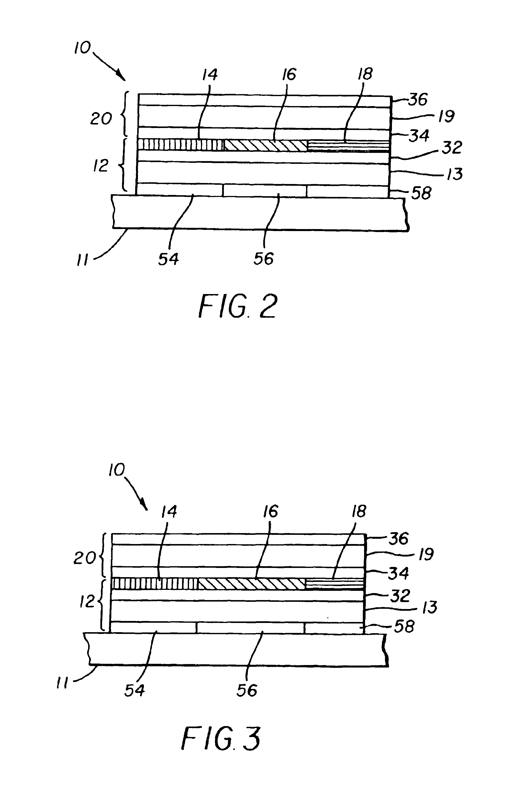
[0017]Referring to FIG. 1a, a top emitting OLED device according to the present invention includes a color pixel 10 located on a substrate 11 having a plurality of individually addressable first white light emitting elements 12R, 12G, 12B; a corresponding plurality of color filters 14, 16, and 18 respectively located over the first white light emitting elements 12R, 12G, 12B to emit colored light. A second separately addressable white light emitting element 20 is located over the color filters. It is possible to use a clear (white light) filter (not shown) in conjunction with the color filters to, for example, improve process or materials stability and layer interactions. Suitable filters are known in the art, for example dichroic filters and absorption filters made of dyes or pigments.

[0018]Alternatively, the OLED device may be bottom emitting (as shown in FIG. 1b) wherein the second white light emitting element 20 is on the substrate 11 and light 25 is emitted through the substrat...


PUM

PropertyMeasurementUnit
Coloraaaaaaaaaa
Sizeaaaaaaaaaa
Areaaaaaaaaaaa

Abstract

An OLED device, having a pixel includes a plurality of individually addressable first white light emitting elements; a corresponding plurality of color filters located over the first white light emitting elements to filter the light emitted by the first white light emitting elements; and a second separately addressable white light emitting element located over the color filters for passing the filtered white light and emitting white light.

Description

FIELD OF THE INVENTION[0001]The present invention relates to OLED color displays and, more particularly, to arrangements of light emitting elements in the pixels of such OLED color displays.BACKGROUND OF THE INVENTION[0002]U.S. application Ser. No. 2002 / 0186214A1, by Siwinski, published Dec. 12, 2002, shows a method for saving power in an organic light emitting diode (OLED) display having pixels comprised of red, green, blue and white light emitting elements. The white light emitting elements are more efficient than the other colored light emitting elements and are employed to reduce the power requirements of the display.[0003]OLED devices age as current passes through the emissive materials of the display. Specifically, the emissive materials age in direct proportion to the current density passing through the materials. Hence, the solution proposed by Siwinski will have the effect of either reducing the size of the emissive elements (if four elements occupy the same area as three e...

Claims


Application Information

Patent Timeline
IPC IPC(8): H05B33/14H05B33/24H05B33/26G09G3/32H01J1/62H01L27/32H01L51/00H01L51/50H05B33/00
CPCG09G3/3216G09G3/3225H01L51/5036H01L27/3213H01L27/322G09G3/3208G09G2300/0452G09G2320/0666G09G2330/021G09G2320/043H10K59/351H10K59/38H10K50/125
Inventor COK, RONALD S.
Owner GLOBAL OLED TECH
Why Eureka
Try Eureka