Electromagnetic coupler flexible circuit with a curved coupling portion

a flexible circuit and coupler technology, applied in the direction of waveguide devices, high frequency circuit adaptations, instruments, etc., can solve the problems of inability to use computer systems, inconvenient use, and inability to meet the needs of the user,

Inactive Publication Date: 2006-01-17
INTEL CORP
View PDF16 Cites 17 Cited by
  • Summary
  • Abstract
  • Description
  • Claims
  • Application Information

AI Technical Summary

Problems solved by technology

Conventional coupling devices suffer from deficiencies in several areas.
Therefore,...

Method used


Image

  • Electromagnetic coupler flexible circuit with a curved coupling portion
  • Electromagnetic coupler flexible circuit with a curved coupling portion
  • Electromagnetic coupler flexible circuit with a curved coupling portion

Examples


Embodiment Construction

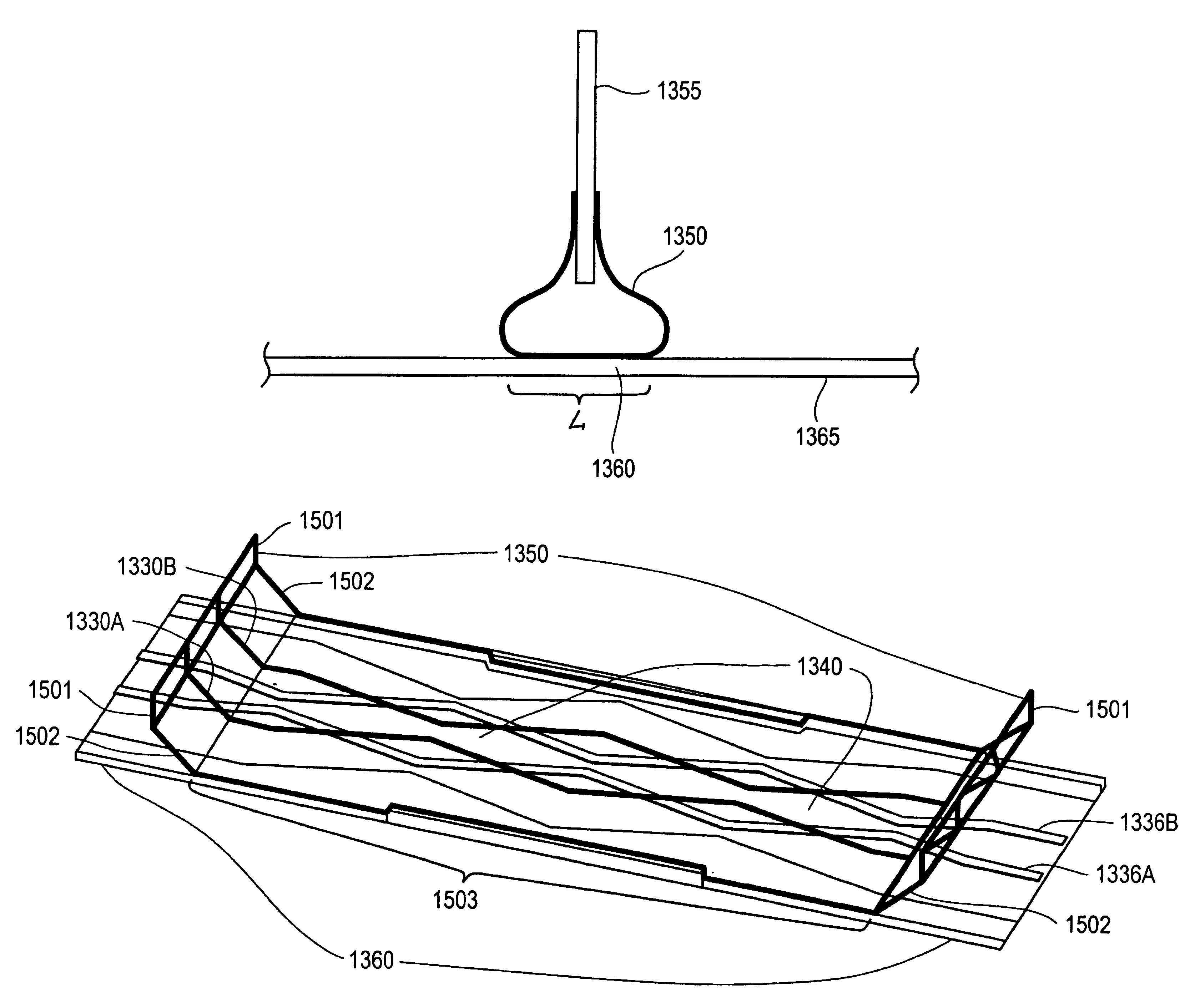
[0019]An electromagnetic (EM) coupler is disclosed. For one embodiment, the EM coupler includes a first transmission structure having a first geometry and a second transmission structure having a second geometry, which may be different than the first geometry. An EM coupling is formed between the first and second transmission structures. For one embodiment, the first and second geometries are selected to reduce sensitivity of EM coupling to relative positions of the first and second transmission structures. The EM coupler structure may be physically separated into two component halves to be used in an interconnect application.

[0020]For one embodiment, the EM coupler provides a broadband coupling device that is separable, bi-directional, and provides robust performance despite misalignment of the transmission structures. The coupler may further have an impedance that is controlled over a wide frequency range to prevent losses from reflections. Thus, the coupler may be used to transmi...


PUM


Abstract

An electromagnetic (EM) coupler including a first transmission structure having a first geometry, and a second transmission structure having a second geometry and forming an EM coupler with the first transmission structure, the first and second geometries being selected to reduce sensitivity of EM coupling to relative positions of the first and second transmission structures is disclosed.

Description

CROSS-REFERENCE TO RELATED APPLICATION[0001]This application is a continuation of U.S. patent application Ser. No. 09 / 714,899, filed on Nov. 15, 2000, now U.S. Pat. No. 6,573,801, issued Jun. 3, 2003.FIELD OF INVENTION[0002]This invention is related to the field of electromagnetic coupling devices for bus communication.BACKGROUND OF THE INVENTION[0003]Electromagnetic coupling devices enable energy to be transferred between components of a system via interacting electric and magnetic fields. These interactions are quantified using coupling coefficients. The capacitive coupling coefficient is the ratio of the per unit length coupling capacitance, Cm, to the geometric mean of the per unit length capacitances of the two coupled lines, Cl. Similarly, the inductive coupling coefficient is the ratio of the per unit length mutual inductance, Lm, to the geometric mean of the per unit length inductances of the two coupled lines, Ll.[0004]FIG. 1 shows a conventional broadside coupler in a spac...

Claims


Application Information

Patent Timeline
IPC IPC(8): H01P5/12H01P5/18H05K1/02H05K1/14
CPCH01P5/185H01P5/187H05K1/0228H05K1/0239H05K1/0237H05K2201/097H05K1/0245H05K1/14H05K2201/09263H01P5/12
Inventor MARKETKAR, NANDU J.KNIGHT, JR., THOMAS F.BENHAM, JOHN R.AMIRTHARAJAH, RAJEEVAN
Owner INTEL CORP
Why Eureka
Try Eureka