Power line communications method

a power line and communication method technology, applied in the field of powerline communications, can solve the problems of high cost of such modems, high speed and high cost of power line modems, and the inability to meet the needs of data switching details,

Inactive Publication Date: 2006-01-17
RESIDUAL BUSINESS MANAGEMENT
View PDF5 Cites 128 Cited by
  • Summary
  • Abstract
  • Description
  • Claims
  • Application Information

AI Technical Summary

Benefits of technology

[0007]Typically, modulation of the current component of the AC power signal will be such that 1 bit or less will be transmitted for each half sine of the AC power signal. Embodiments of this type are advantageous as they permit simple amplitude modulation of each half sine to be performed, whereby a demodulator can simply detect a peak amplitude of each half sine to determine an amplitude variation of the current component of the AC power signal.
[0010]Further, due to the direct modulation of a power signal, power may be shifted within or between half sines of the AC power signal. Ideally, a modulation scheme is chosen to minimise or eliminate any power consumption which may be caused by the shifted power. For instance, it may be preferable to cause the power shift to occur between half sines rather than between full sines.
[0013]It is to be noted that the method of the first aspect of the present invention allows communications to occur both in the direction of power flow, and against the direction of power flow. For instance, in a domestic environment, power may flow from a commercial power distribution grid to appliances (loads) in a household, and power may pass from on-site power sources, such as a photovoltaic system, to the grid. Both involve the use of a grid interface unit (GIU), connected between the loads / sources and the grid. In such an environment, communications may be desired between the GIU and both the loads and the sources. As will be readily apparent, a power source such as the photovoltaic system need merely be operable to produce AC power with amplitude modulation of the current component of the AC power signal. Such modulation enables the GIU to determine the information transmitted by the source.
[0019]The second aspect of the present invention is of particular advantage where it is desired to monitor one or more appliances. In such embodiments, most communications would typically take place in the on-line mode, as most information would consist of status signals passing from the appliance(s) to the monitoring unit. Such embodiments of the second aspect of the present invention allow the monitoring to take place without significant interruption of power, and without the need to use a separate communications line or a power line modem.

Problems solved by technology

However, the circuitry of such modems must be able to withstand the large power levels present on the power lines, and the cost of such modems is usually significantly higher than standard modems which can be used where dedicated communications cabling is available, thereby offsetting some of the cost savings in using only a single line for both power and communications.
Furthermore, devices connected to the power line are often quite simple in nature and consequently the required rate of communications will be extremely low, as only relatively small amounts of information need to be transmitted.
In such situations, the high speed and high cost of a power line modem will go substantially unutilised.

Method used


Image

  • Power line communications method
  • Power line communications method
  • Power line communications method

Examples


Embodiment Construction

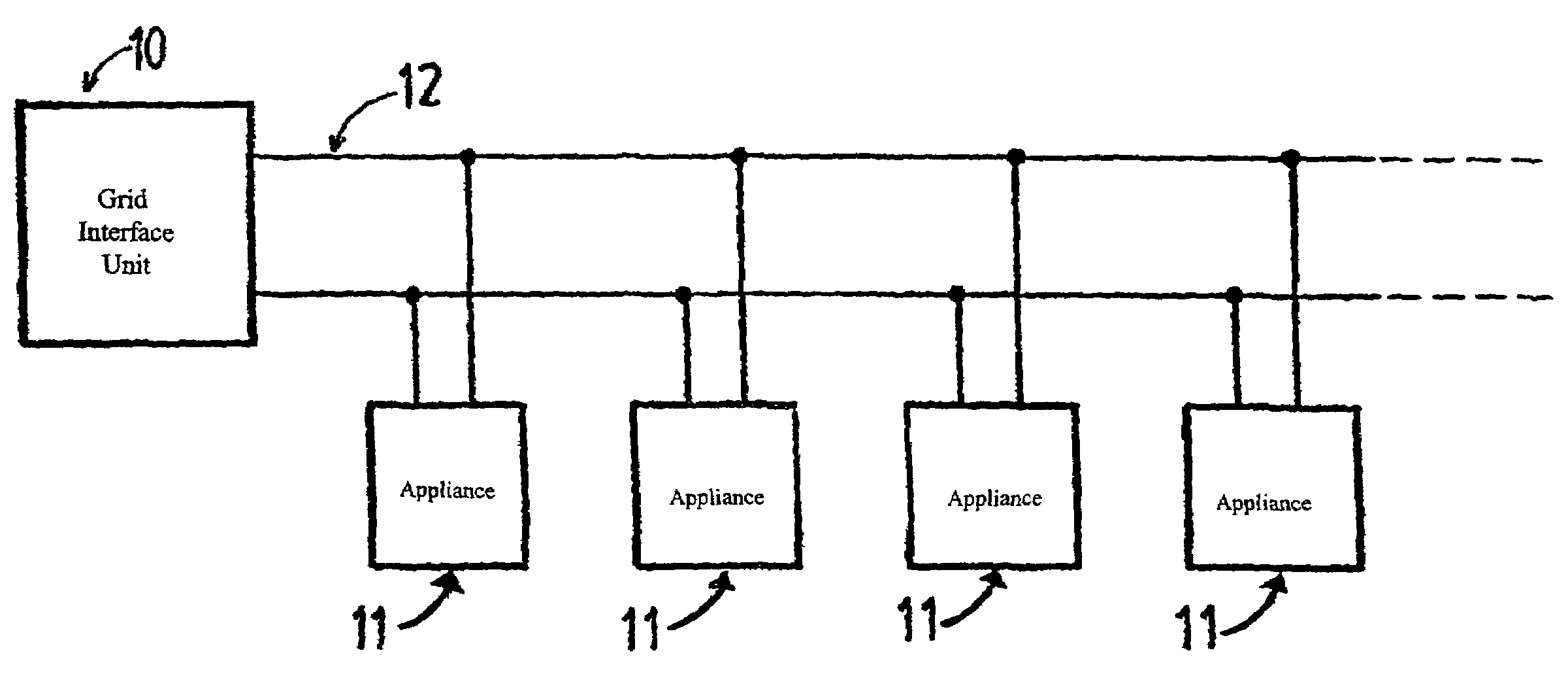
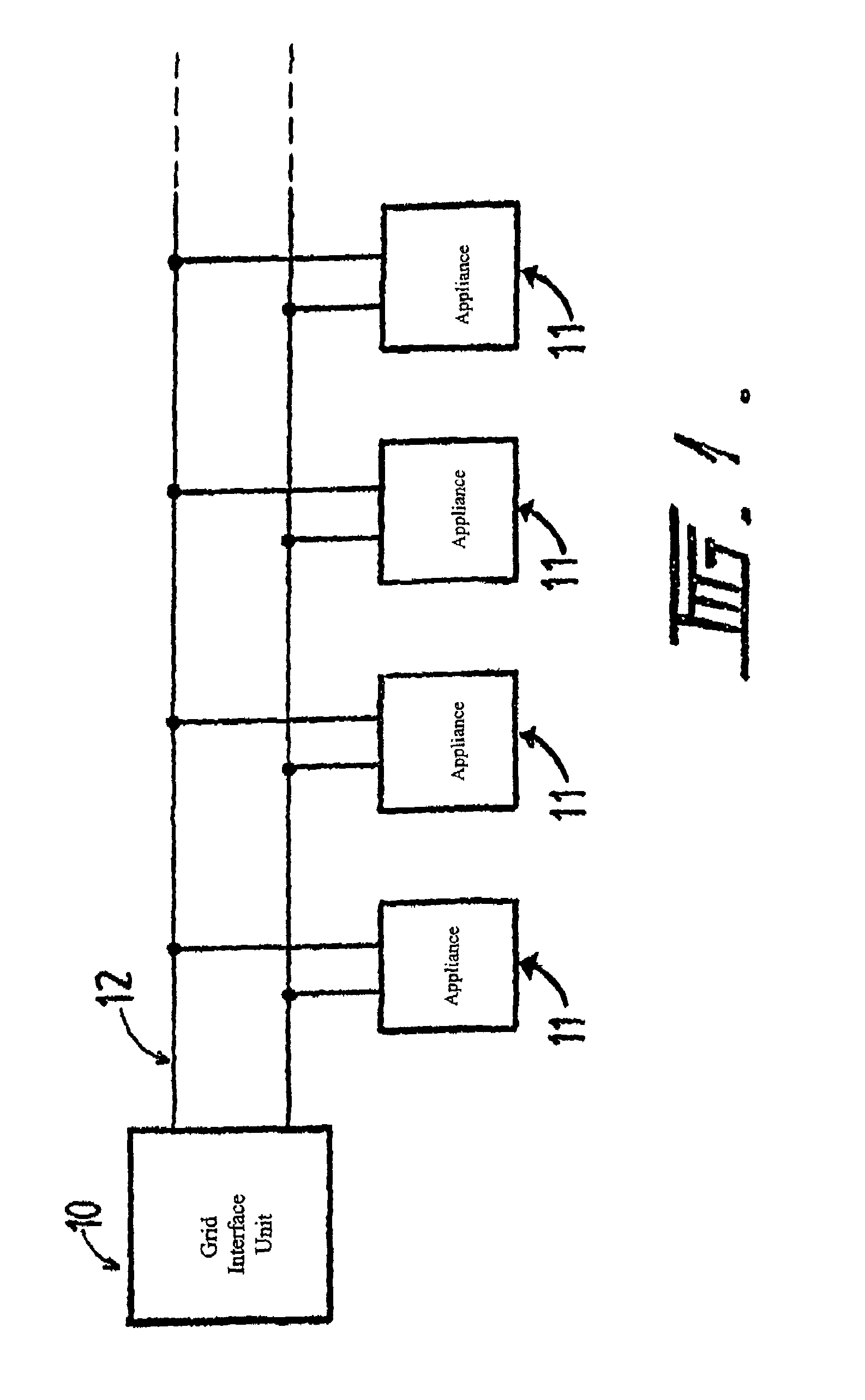
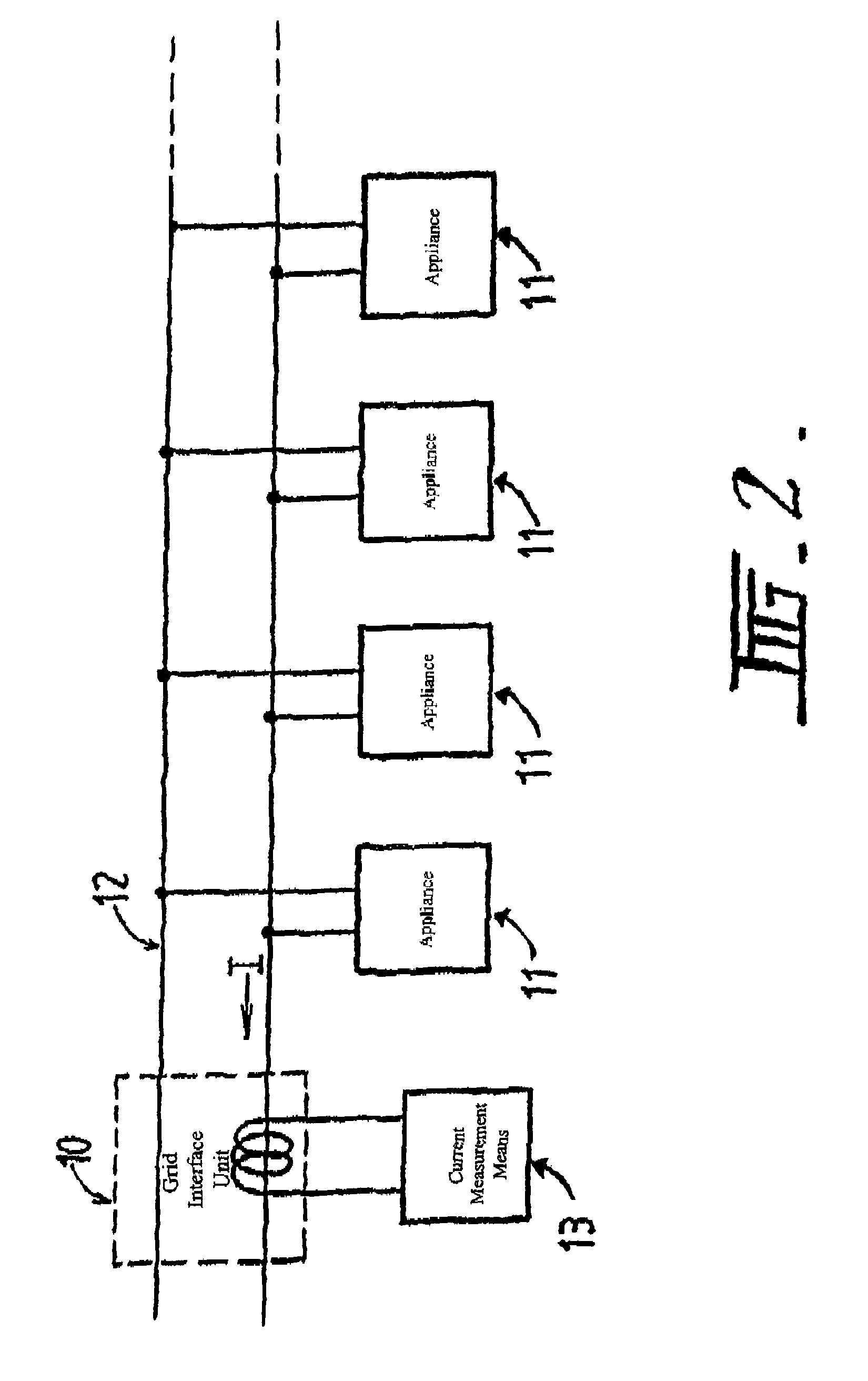
[0029]FIG. 1 illustrates an embodiment of the invention in which a grid interface unit 10 is operable to communicate with a plurality of appliances 11 over power line 12. Communications between the grid interface unit 10 and the appliances 11 are conducted in accordance with the communications protocol of the second aspect of the present invention. During the first mode of operation, on-line communications are conducted in a single direction, from the appliances 11 to the grid interface unit 10, by modulation of a current component of a power signal passed between the grid interface unit 10 and the appliances 11. Hence, during the first mode of operation, there is provided a simplex (one-way) channel from the appliances to the grid interface unit.

[0030]As can be seen, the present invention is of particular advantage where it is desired to monitor one or more appliances, particularly as the monitoring can be performed by a pre-existing component in the power system, namely the GIU 10...


PUM


Abstract

A method of communicating over a power line is disclosed, the method comprising the step of modulating a current component of an AC power signal present on the power line. Also disclosed is a communications protocol for communication between a monitoring unit and an appliance, the protocol having two modes of operation, the first mode being an on-line single direction protocol for communications from the appliance to the monitoring unit via modulation of a current component of an AC power signal between the monitoring unit and the appliance, and the second mode being an off-line protocol for communications at least from the monitoring unit to the appliance, the second mode being operable only when the power signal is not present between the monitoring unit and the appliance.

Description

[0001]This application is a 371 of PCT / AU01 / 00818 filed on Jul. 6, 2001.TECHNICAL FIELD[0002]The present invention relates to power-line communications, and is applicable to both sources and loads.BACKGROUND OF THE INVENTION[0003]In situations where power lines exist between two devices which wish to communicate to each other, it has been recognised that the existing power lines may be used both for power transmission and communications, thereby avoiding the need to install separate communication cabling. In the past, this has been achieved by way of high speed power line modems, which are capable of connecting to the power line and inserting a carrier signal onto the power lines and additional to the power signal, and modulating the carrier signal with information to be transmitted. However, the circuitry of such modems must be able to withstand the large power levels present on the power lines, and the cost of such modems is usually significantly higher than standard modems which ...

Claims


Application Information

Patent Timeline
Patent Type & Authority Patents(United States)
IPC IPC(8): H04M11/04H04B3/54H02J13/00H04B3/56H04L12/40
CPCH04B3/54H04B3/56H04L12/403H04L12/10H04B2203/5487H04B2203/5412
Inventor BUB, STEPHEN LEONARDRANNARD, WILLIAM DOUGLAS
Owner RESIDUAL BUSINESS MANAGEMENT
Why Eureka
Try Eureka