Display panel driver

a technology for display panels and drivers, applied in the field of display panel drivers, can solve the problems of power consumption and increase in power consumption in the addressing step, and achieve the effect of reducing power consumption

Inactive Publication Date: 2006-01-17
PANASONIC CORP
View PDF5 Cites 6 Cited by
  • Summary
  • Abstract
  • Description
  • Claims
  • Application Information

AI Technical Summary

Benefits of technology

[0007]In view of the above-described problems, it is an object of the present invention to provide a display panel driver with which the power consumption can be reduced.

Problems solved by technology

In plasma display devices, discharges are induced during the emission sustaining step for the actual image display, but also during the addressing step, and the current flowing in the course of this discharge leads to the consumption of power.
Thus, there is the problem that, depending on the input video signal that specifies the image to be displayed, the power that is consumed in the addressing step may increase.

Method used


Image

  • Display panel driver
  • Display panel driver
  • Display panel driver

Examples


Embodiment Construction

[0026]The following is an explanation of embodiments of the present invention, with reference to the accompanying drawings.

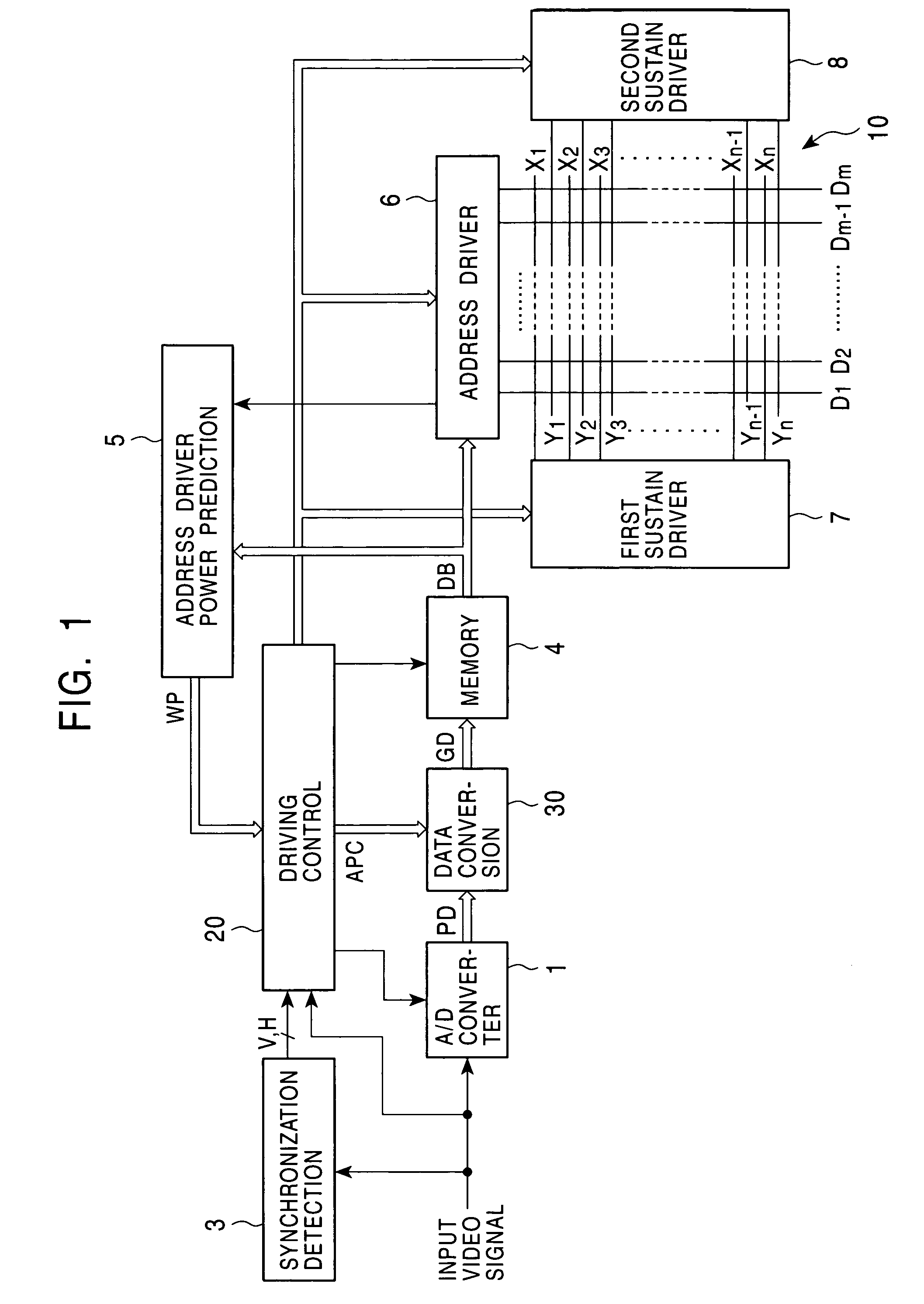
[0027]FIG. 1 is a diagram illustrating the general configuration of a plasma display device equipped with a display panel driver according to the present invention.

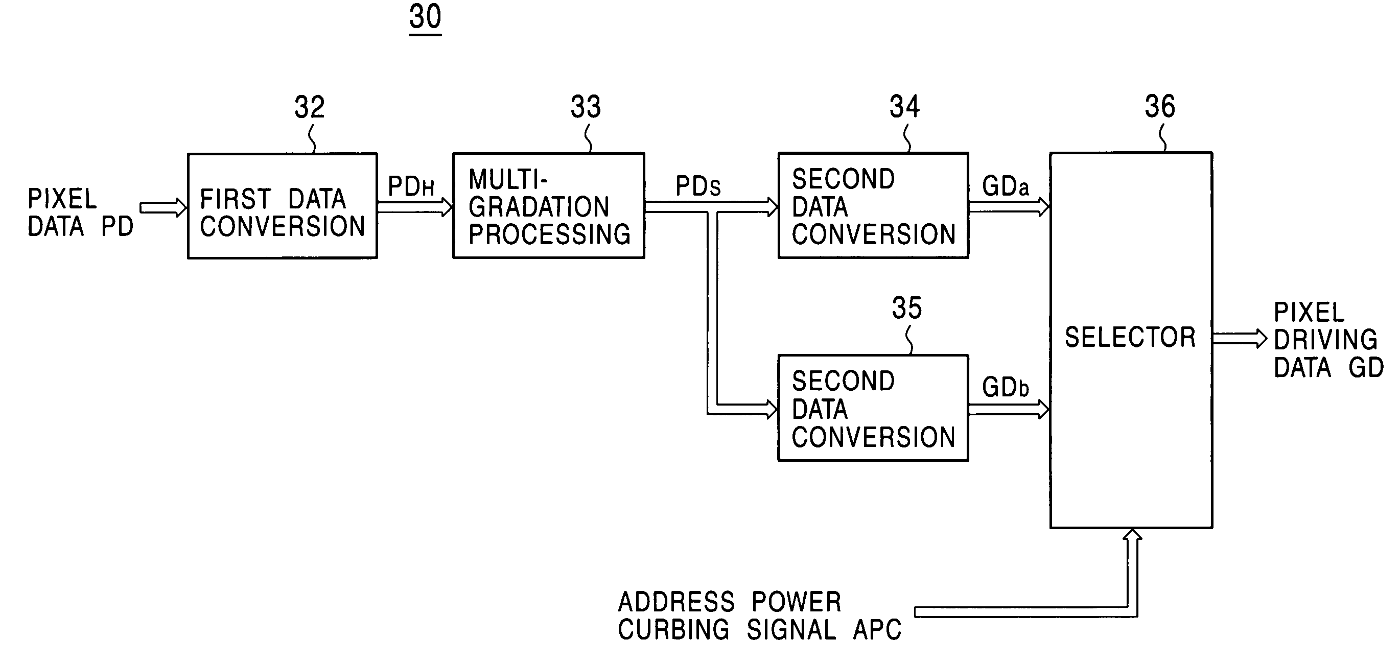
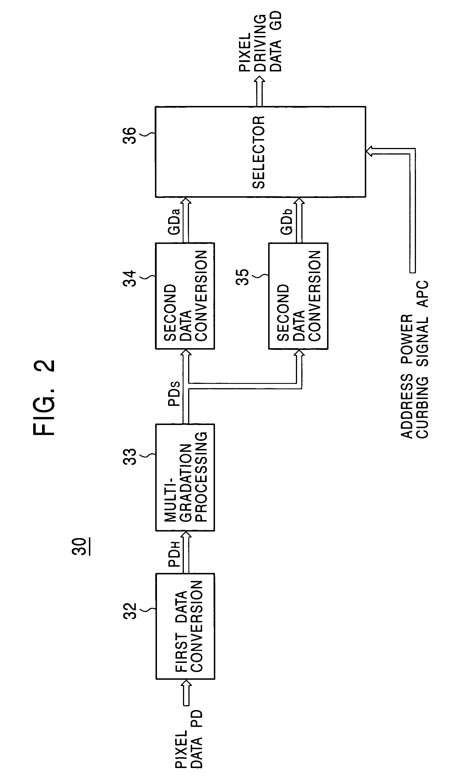
[0028]This plasma display device includes a PDP 10 serving as a plasma display panel, an A / D converter 1, a driving control circuit 20, a synchronization detection circuit 3, a memory 4, an address driver power prediction circuit 5, an address driver 6, a first sustain driver 7 and a second sustain driver 8.

[0029]The PDP 10 includes band-shaped row electrodes X1 to Xn and row electrodes Y1 to Yn that are arranged in alternation and parallel to one another on a transparent front substrate serving as the display screen, and band-shaped column electrodes D1 to Dm that are arranged on the rear substrate, intersecting with the row electrodes. A heat sink is fixed to the rear substrate. The column electrode...


PUM


Abstract

It is an object of the present invention to provide a display panel driver with which power consumption can be reduced. The display panel driver includes a pixel data pulse generation circuit which generates pixel data pulses by connecting the column electrodes and a power source line in accordance with the pixel data to apply the pixel data pulses to the column electrodes, and a resonance pulse power circuit which generates a resonance pulse power source voltage to apply the resonance pulse power source voltage to the power source line, the resonance pulse power circuit changing the resonance amplitude of the resonance pulse power source voltage while keeping a maximum voltage of the resonance pulse power source voltage in accordance with a pattern of a pulse sequence of the pixel data pulses. A predicted power consumption of the resonance pulse power circuit is determined based on the pixel data for one field, and the pixel data pulse generation circuit is controlled so as to adjust the power consumption of the resonance pulse power circuit in accordance with the predicted power consumption.

Description

BACKGROUND OF THE INVENTION[0001]1. Field of the Invention[0002]The present invention relates to a display panel driver.[0003]2. Description of the Related Art[0004]In recent years, as the screens of display devices become larger, there is also a demand for thinner display devices, and various kinds of thin display devices have been put into practice. Plasma display panels (referred to in the following as “PDP”) have garnered attention as one type of thin display panel in which a plurality of discharge cells serving as pixels are arranged in a matrix. The discharge cells emit light by discharges, so that only two states, namely a “lighted state” in which they emit light at a predetermined luminance and an “unlighted state,” and thus only the luminance for two gradations, can be realized. In order to address this problem, a PDP 10 provided with such discharge cells is subjected to gradation driving using the sub-field method, which is supposed to realize the display of intermediate l...

Claims


Application Information

Patent Timeline
Patent Type & Authority Patents(United States)
IPC IPC(8): G09G5/00G09G3/20G09G3/288G09G3/291G09G3/292G09G3/293G09G3/296G09G3/298H01J11/20H01J11/24H01J11/26H04N5/66
CPCG09G3/2022G09G3/2927G09G3/293G09G3/2932G09G3/2935G09G3/2944G09G3/2965G09G3/2937G09G2360/16G09G2310/066G09G2320/103G09G2330/021
Inventor IWAMI, TAKASHIYUASA, TOYOHISAOKUSHIMA, TAKASHISHIGETA, TETSUYANAGAKUBO, TETSURO
Owner PANASONIC CORP
Why Eureka
Try Eureka