Image signal conversion apparatus, method and display for image signal conversion based on selected pixel data

Inactive Publication Date: 2006-01-17
SONY CORP
View PDF17 Cites 17 Cited by
  • Summary
  • Abstract
  • Description
  • Claims
  • Application Information

AI Technical Summary

Benefits of technology

[0036]Moreover, when the second image signal is supplied to the image display device having image quality adjustment functions such as contrast and sharpness and the image display device displays an image formed from the second image signal, these functions are invalidated. O

Problems solved by technology

Although the HDTV has such excellent characteristics, the image according to the HDTV system cannot be displayed on the HDTV television receiver as if a video signal of NTSC system is supplied to the HDTV television receiver as it is.
In the above-described conversion apparatus, however, the resolution of an image according to the video signal of the HDTV system is fixed and this fails to adjust the resolution to the desired one corresponding to the image contents or the like as the conventional adjustments for contrast, sharpness and the like.
Moreover, in the above-described conversion apparatus, an image quality of an image formed from the video signal of the HDTV system is fixed and this fails to obtain the image quality to which the respective users prefer.
Therefore, the user has been required to separately perform a few kinds of adjustments for contrast, sharpness and the like, which have been troublesome.
Therefore, the user has been required to separately adjust contrast, sharpness and the like by, for example, the image-quality-adjustment-function provided to the image display device so as to obtain the image quality adaptable for the image display device, which have been troublesome.

Method used


Image

  • Image signal conversion apparatus, method and display for image signal conversion based on selected pixel data
  • Image signal conversion apparatus, method and display for image signal conversion based on selected pixel data
  • Image signal conversion apparatus, method and display for image signal conversion based on selected pixel data

Examples


Embodiment Construction

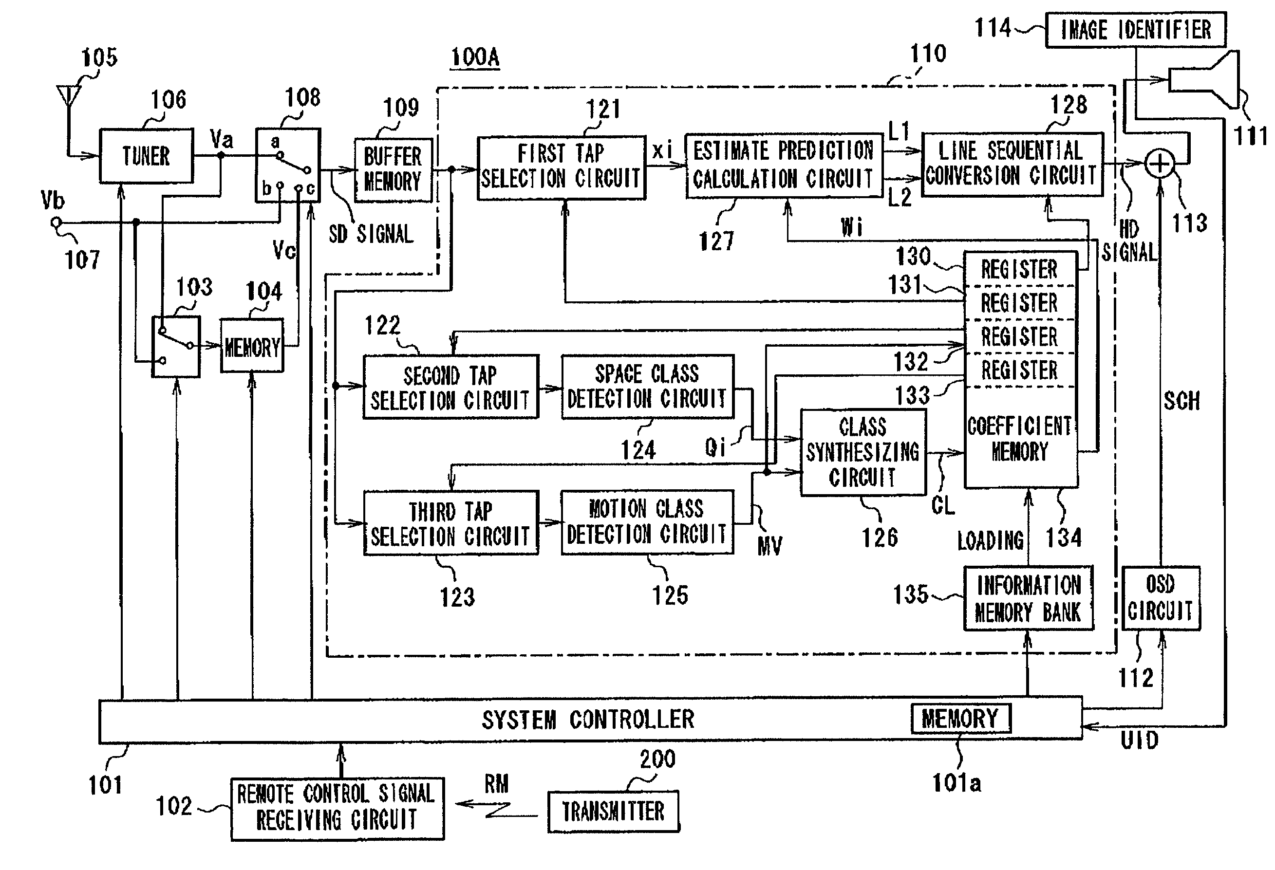
[0061]FIG. 1 shows a configuration of a television receiver 100 as an preferred embodiment of the present invention. The television receiver 100 obtains as SD (Standard Definition) signal of 525i signal from a broadcasting signal, the 525i signal is then converted to a HD (High Definition) signal of 525p signal or 1050i signal, and the television receiver displays an image formed from its 525p signal or 1050i signal.

[0062]Now, 525i signal is referred to an image signal for scanning the number of lines of 525 by interlace method, 525p signal is referred to an image signal for scanning the number of lines of 525 by progressive method (non-interlace method), and 1050i signal is referred to an image signal for scanning the number of lines of 1050 by interlace method.

[0063]The television receiver 100 comprises a system controller 101 with a microcomputer for controlling operations of the entire system and a remote control signal receiving circuit 102 for receiving remote control signal. ...


PUM


Abstract

The present invention relates to an image signal conversion apparatus or the like preferably applied, for example, when a SD signal (525i) is converted into a HD signal (525p or the like). In the image signal conversion section (110), the SD signal is converted into the HD signal, and the image is displayed on the display section (111). A class code CL indicating a class of a subject pixel of the HD signal is obtained by detecting a space class and a motion class from tap pixel data corresponding to the subject pixel of HD signal which is selectively fetched from a SD signal. The controller (101) loads coefficient data of each class according to the selected resolution into the coefficient memory (134) from the information memory bank (135) when the user selects the resolution. In the calculation circuit (127), pixel data of the subject pixel of the HD signal is calculated using an estimating equation based on the tap data xi corresponding to the subject pixel of the HD signal selectively fetched from the SD signal in the tap selection circuit (121) and the coefficient data wi read in class code CL from the coefficient memory (134).

Description

TECHNICAL FIELD[0001]The present invention relates to an image signal conversion apparatus, an image signal conversion method, an image display apparatus using the same, and a coefficient data generating apparatus used therein, which are preferably used, for example, when a video signal of NTSC system is converted into a video signal of high definition television (hereinafter called “HDTV”).BACKGROUND ART[0002]In recent years, because of the enhanced audio visual oriented trend, the development of a television receiver capable of displaying the image having a higher resolution has been desired so that the above HDTV can be developed corresponding to this demand. The number of scanning lines of the HDTV system is 1,125 lines, which is 2-fold or more compared with the number of scanning lines of 525 of NTSC system. Moreover, as for the aspect ratio, the ratio of the HDTV system is 9:16 while the one of NTSC system is 3:4. Therefore, according to the HDTV system, the image having a hig...

Claims


Application Information

Patent Timeline
IPC IPC(8): H04N11/00H04N5/44H04N7/01
CPCH04N7/0125H04N21/4854H04N21/440218H04N7/0137H04N5/44H04N7/0145
InventorKONDO, TETSUJIROTAKAHASHI, KENJIYOSHIKAWA, KAZUSHI
OwnerSONY CORP