
Method and apparatus for media thermal decay measurement in a disk drive

a technology of disk drive and media thermal decay, which is applied in the direction of magnetic recording, instruments, data recording, etc., can solve the problems of inability to read the read head properly, information stored on the disk surface may be lost, and the information stored on the disk surface may begin to decay

Inactive Publication Date: 2006-01-17
MAXTOR
View PDF4 Cites 25 Cited by
  • Summary
  • Abstract
  • Description
  • Claims
  • Application Information

AI Technical Summary

Problems solved by technology

Ultimately, if a threshold number of grains change their direction of magnetization, information stored on the disk may be lost.
Because the superparamagnetic effect may occur at room temperature, over time, information stored on the disk surface will begin to decay.
Once the stored information decays beyond a threshold level, it will be unable to be properly read by the read head and the information will be lost.
Decreases in the quality of the readback signal cause bit error rate (BER) increases.
However, as noted above, the path of progress has been against stable media (e.g., grain sizes are being reduced to allow more information to be stored on a disk surface).
However, spin stand measurements are largely disfavored because expensive pieces of equipment are tied-up for long periods of time (e.g., many hours), thereby increasing overall manufacturing costs and, hence, the cost of disk drives to end users.

Method used


Image

  • Method and apparatus for media thermal decay measurement in a disk drive
  • Method and apparatus for media thermal decay measurement in a disk drive
  • Method and apparatus for media thermal decay measurement in a disk drive

Examples


Embodiment Construction

[0027]While this invention is susceptible of embodiments in many different forms, there are shown in the drawings and will herein be described in detail, preferred embodiments of the invention with the understanding that the present disclosure is to be considered as an exemplification of the principles of the invention and is not intended to limit the broad aspects of the invention to the embodiments illustrated.

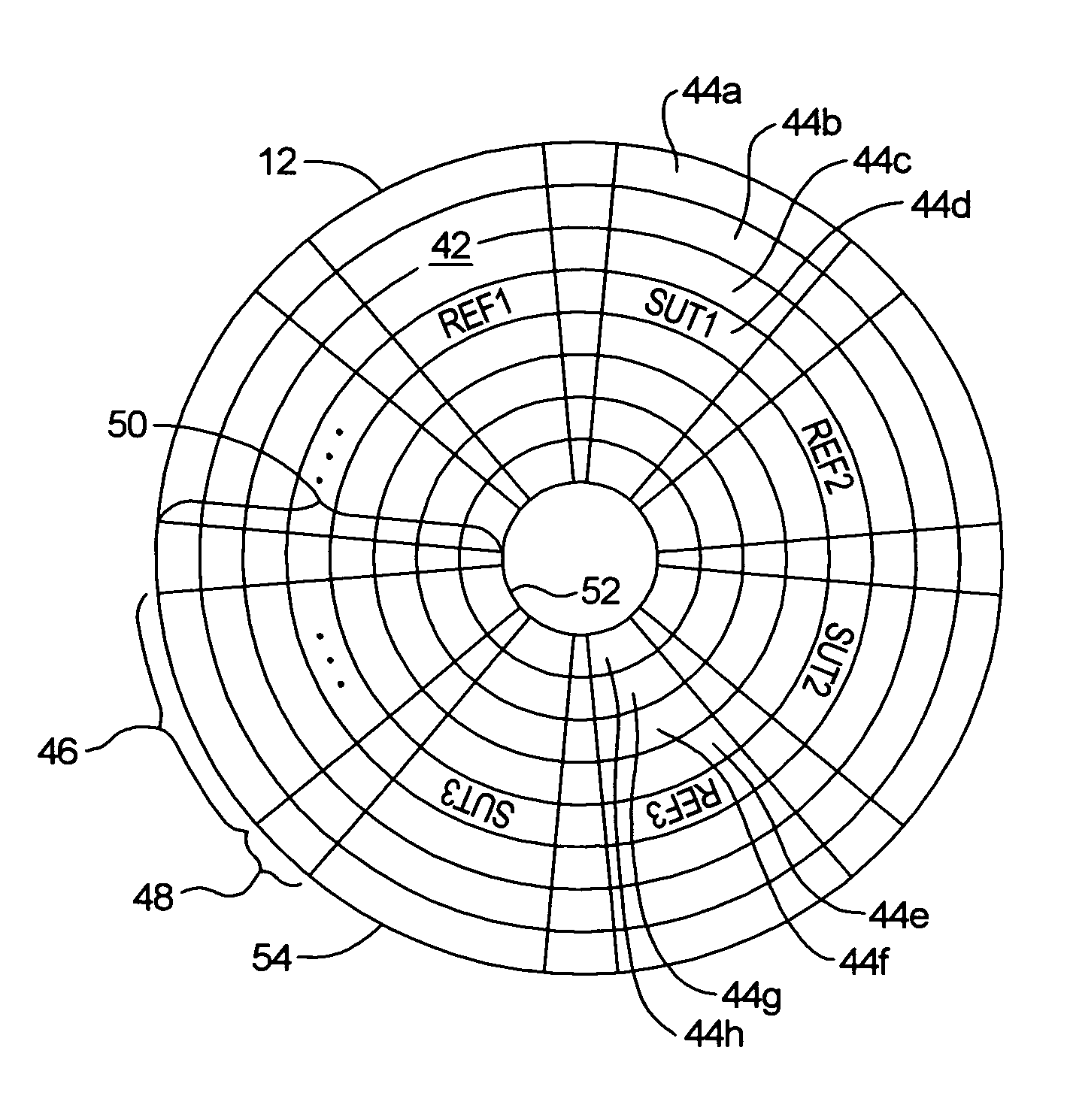
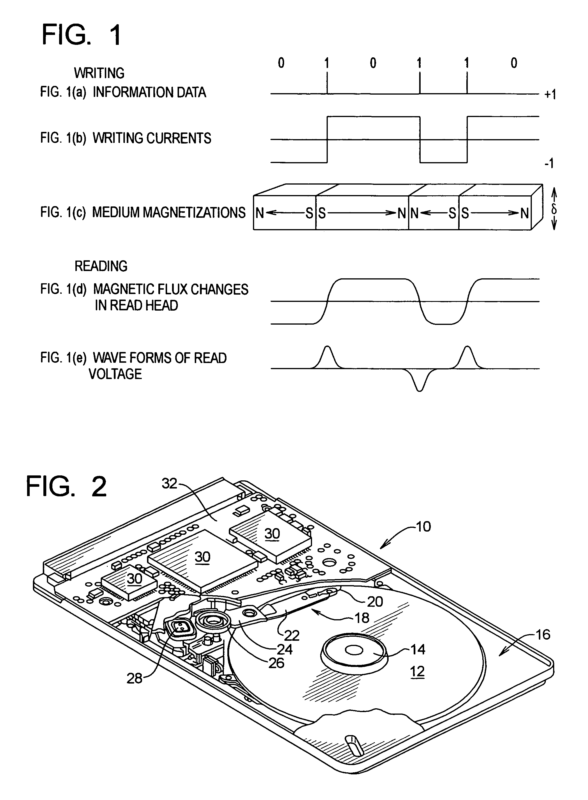
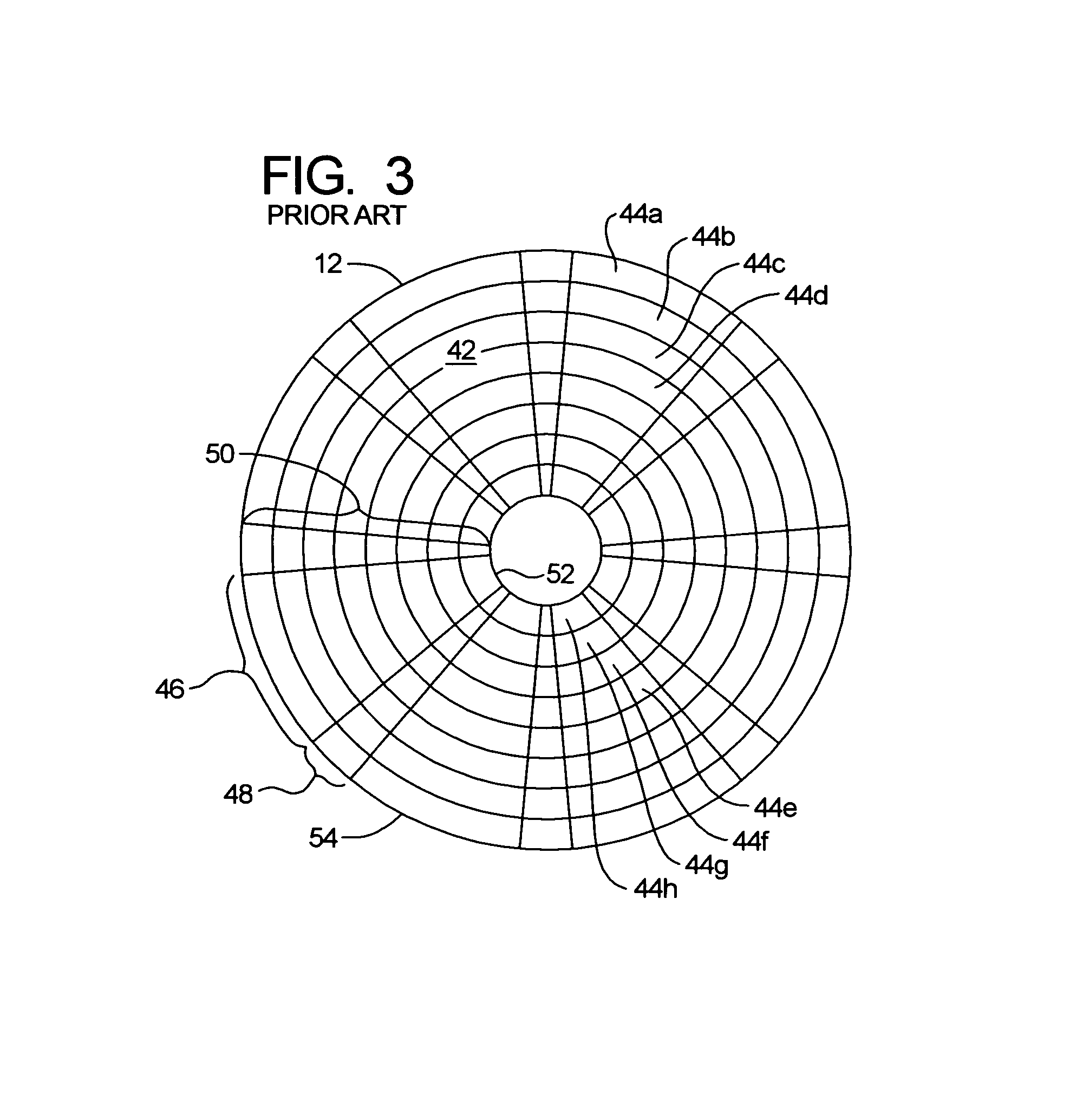
[0028]A disk drive 10 with which the present invention may be used is illustrated in FIG. 2. The disk drive comprises a disk 12 that is rotated by a spin motor 14. The spin motor 14 is mounted to a base plate 16.

[0029]The disk drive 10 also includes an actuator arm assembly 18 having a head 20 (or transducer) mounted to a flexure arm 22, which is attached to an actuator arm 24 that can rotate about a bearing assembly 26 that is attached to the base plate 16. The actuator arm 24 cooperates with a voice coil motor 28 in order to move the head 20 relative to the disk 12. The sp...


PUM

PropertyMeasurementUnit
timeaaaaaaaaaa
diameteraaaaaaaaaa
diameteraaaaaaaaaa

Abstract

A method and apparatus is provided for measuring a media thermal decay rate for a disk in a disk drive. In one embodiment, reference patterns are written in a plurality of reference sectors on a test track of a disk surface. A thermal decay measurement duration is predetermined. After at least two decades of time longer than the predetermined thermal decay measurement duration have passed since writing the reference patterns in the plurality of reference sectors, sector-under-test patterns are written in a plurality of sectors-under-test, wherein the sectors-under-test and the reference sectors are written in data sectors and alternate with one another about at least a portion of the test track. The mean square error is measured and averaged for the reference sectors, and the mean square error is measured and averaged for the sectors under test. The averaged mean square error for the reference sectors and the averaged mean square error for the sectors-under-test are used to calculate the media thermal decay rate. In another embodiment, information associated with the amplitude of the readback signal is used instead of, or in addition to, the mean square error of the readback signal to calculate the media thermal decay rate.

Description

CROSS-REFERENCE TO RELATED APPLICATIONS[0001]Priority is claimed from U.S. Provisional Patent Application Ser. No. 60 / 356,905 filed Feb. 12, 2002, which is incorporated herein by reference in its entirety.FIELD OF THE INVENTION[0002]The present invention relates to magnetic storage devices and, more particularly, to computer disk drives. More specifically, the present invention relates to a method and apparatus for media thermal decay measurement in a disk drive.BACKGROUND OF THE INVENTION[0003]Computer disk drives store digital information on magnetic disks which are coated with a magnetic material that is capable of changing its magnetic orientation in response to an applied magnetic field. Typically, the digital information is stored on each disk in concentric tracks that are divided into sectors. Information is written to and read from a disk by a transducer that is mounted on an actuator arm capable of moving the transducer radially over the disk. Accordingly, the movement of t...

Claims


Application Information

Patent Timeline
Patent Type & Authority Patents(United States)
IPC IPC(8): G11B27/36G11B5/02
CPCG11B27/36
Inventor HIGGINS, BILLSCHARDT, BRUCE
Owner MAXTOR
Learn More