
Automatic protection switching using link-level redundancy supporting multi-protocol label switching

a technology of automatic protection switching and label switching, applied in the field of computer networks, can solve the problems of consuming valuable network bandwidth, affecting the convergence affecting the performance of the network as a whole,

Inactive Publication Date: 2006-01-17
RPX CLEARINGHOUSE
View PDF11 Cites 41 Cited by
  • Summary
  • Abstract
  • Description
  • Claims
  • Application Information

AI Technical Summary

Benefits of technology

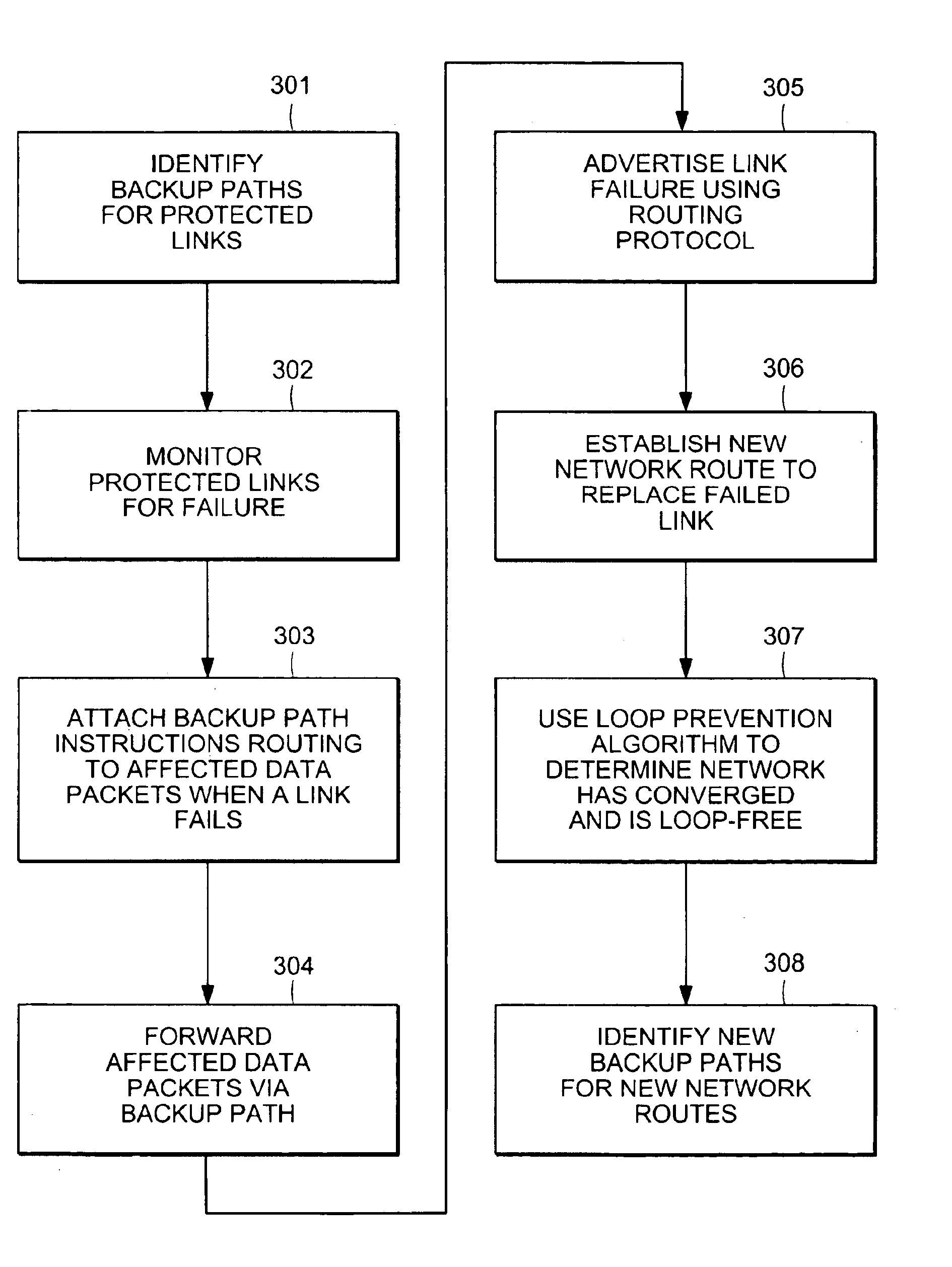
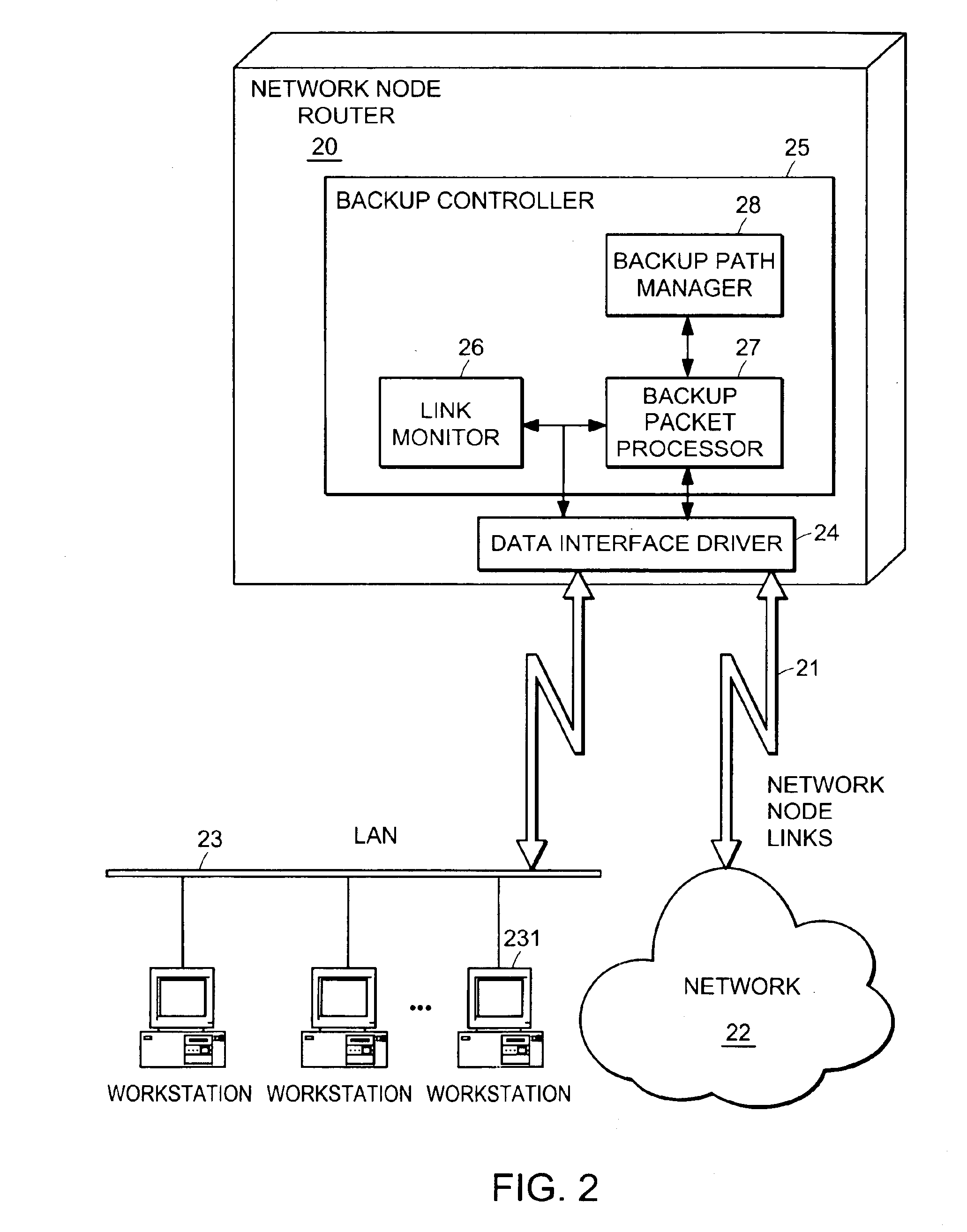
"The patent describes a system for protecting computer networks from link failures, which can cause data to be lost or become inaccessible. The system uses a backup controller that identifies backup paths for data packets in case of a failure. When a link fails, the backup controller detects it and attaches instructions to affected data packets, allowing them to be routed through the backup path. This system can be used in data routers and computer networks with multiple data streams. The technical effect of this patent is to provide a reliable and efficient way to protect computer networks from link failures, minimizing the risk of data loss or downtime."

Problems solved by technology

Occasionally, a link between two network routers may fail.
Most routers can detect a local link failure relatively quickly, but it takes the network as a whole a much longer time to converge.
While the network is converging after a link fails, transient loops can occur which consume valuable network bandwidth.
One drawback of loop prevention algorithms, however, is that data packets directed out of a failed link get lost, or “black holed,” during the convergence.
Moreover, since loop prevention algorithms also extend the convergence time somewhat while new routes are being verified to be loop-free, additional data may be lost on the failed link.

Method used


Image

  • Automatic protection switching using link-level redundancy supporting multi-protocol label switching
  • Automatic protection switching using link-level redundancy supporting multi-protocol label switching
  • Automatic protection switching using link-level redundancy supporting multi-protocol label switching

Examples


Embodiment Construction

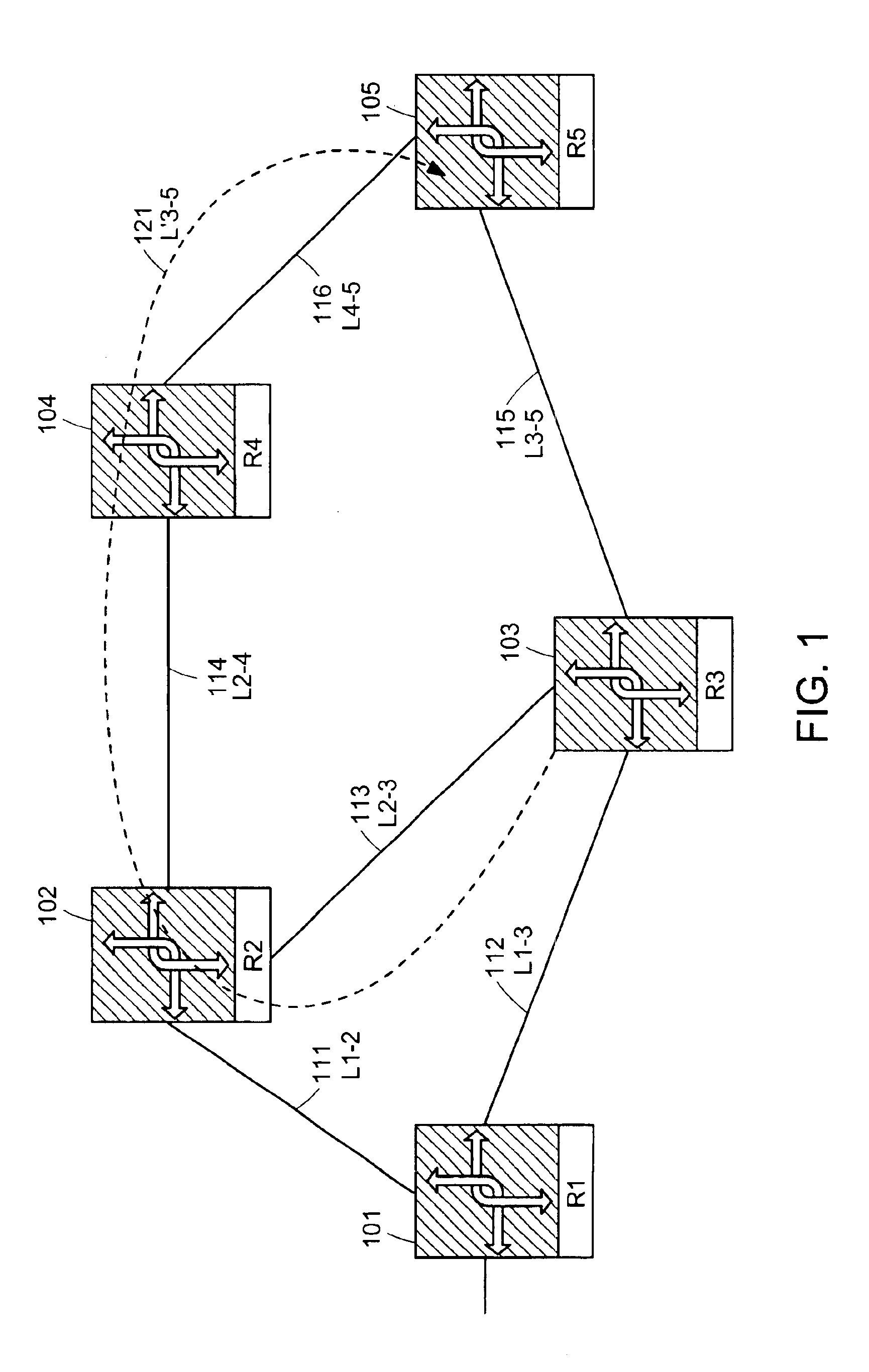
[0017]Representative embodiments of the present invention use a label switching protocol to establish backup paths with explicit routing for use in the event of a link failure in a computer network. A label is a short, fixed length, physically contiguous, locally significant identifier which is used to identify a given data stream in a label switching network. Multi-Protocol Label Switching (MPLS) is an example of a network layer-based label switching routing protocol that uses a forwarding paradigm based on label swapping to forward data traffic. Data forwarding between two adjacent network nodes using MPLS labels is known as a label switched hop. The concatenation of one or more label switched hops defines a Label Switched Path (LSP) that allows data packets to be forwarded from one MPLS node to another MPLS node by swapping labels. Explicit routing of an LSP is when the LSP is specified by the source of a data stream. The sequence of nodes defined by the LSP are defined by a laye...


PUM


Abstract

A computer network has a plurality of routers that deliver data packets to the network via a plurality of links. At least one router provides automatic protection switching in the event of a link failure. The at least one router includes a plurality of data interfaces for streams of data packets to enter and exit the at least one router; and a backup controller. The backup controller includes a backup path manager, a link monitor, and a backup packet processor. For at least one link of the routing node, the backup path manager identifies a backup routing path for forwarding affected data packets in the event of a failure of the at least one link. The link monitor monitors the plurality of links to determine when a link fails. When a link which has a backup routing path fails, the backup packet processor attaches backup routing path instructions to affected data packets routed over the failed link, and forwards the affected data packets via the backup routing path.

Description

[0001]This application is a continuation of U.S. application Ser. No. 09 / 471,463 filed Dec. 22, 1999, which was abandoned Mar. 9, 2004.TECHNICAL FIELD[0002]The present invention relates to computer networks, and more specifically to a computer network that provides protection switching to reroute data packets in the event of a network link failure.BACKGROUND ART[0003]The various links of a computer network are paths between network nodes that communicate streams of data. In an Internet Protocol (IP) based computer network, data routing protocols such as Open Shortest Path First (OSPF), Intermediate System-Intermediate System (IS-IS), and Routing Information Protocol (RIP) are used to determine the path that data packets travel through the network. As a specific example, OSPF is a link-state protocol in the IP suite that enables routers to exchange information regarding topological changes within the network, as the link state database is modified. With this information, each router ...

Claims


Application Information

Patent Timeline
Patent Type & Authority Patents(United States)
IPC IPC(8): H04J1/16H04L1/00H04L12/56
CPCH04L45/00H04L45/22H04L45/28H04L45/50H04W88/14H04W24/00H04W28/04
Inventor FREDETTE, ANDRE N.ANDERSSON, LOADORASWAMY, NAGANANDGHANWANI, ANOOP
Owner RPX CLEARINGHOUSE
Learn More