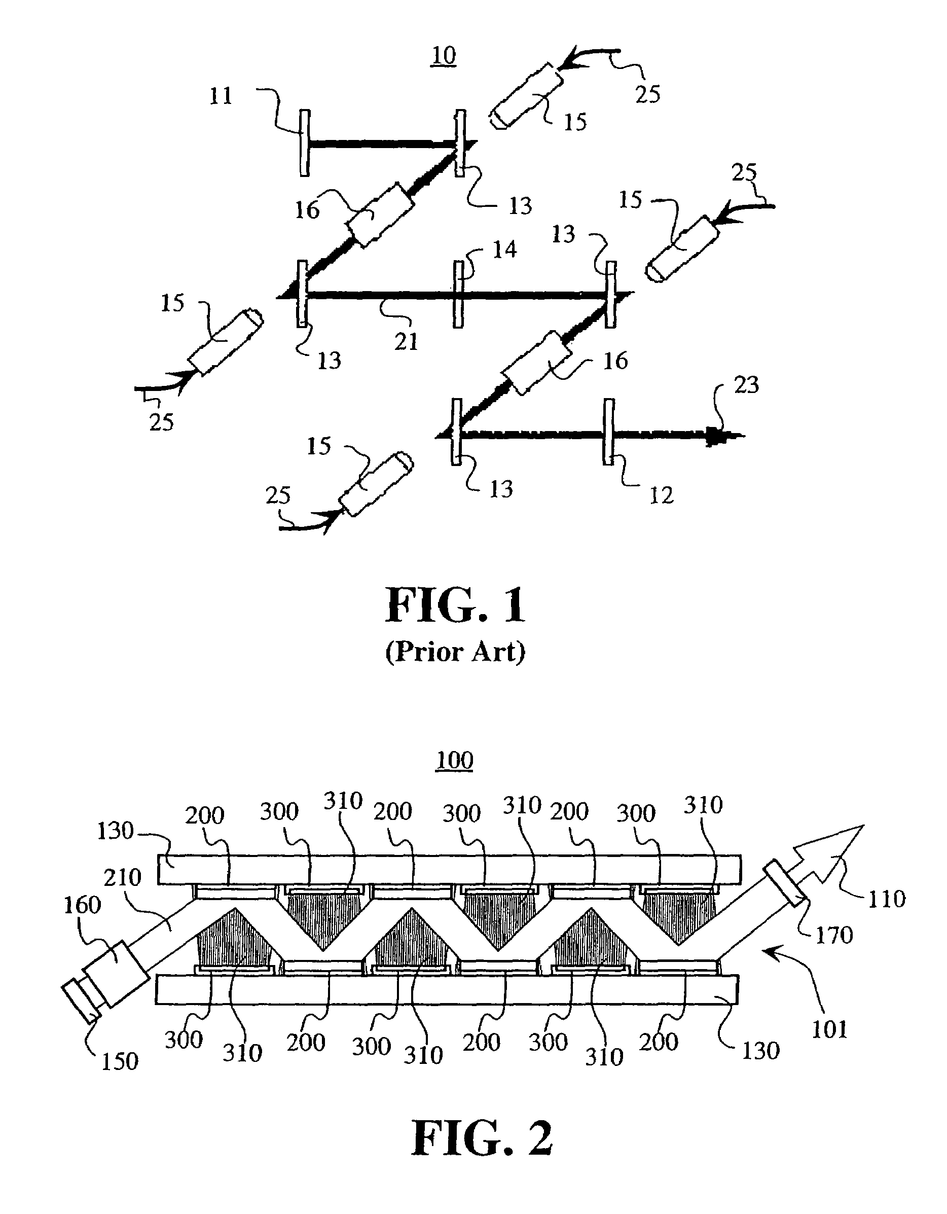
[0017]It is an
advantage of the present invention to provide an apparatus and method for pumping a laser that allows for improved power scaling while minimizing parasitic lasing effects and losses. It is a further
advantage of the present invention to provide a method and apparatus for pumping a laser with a simple geometry and to minimize the components used.
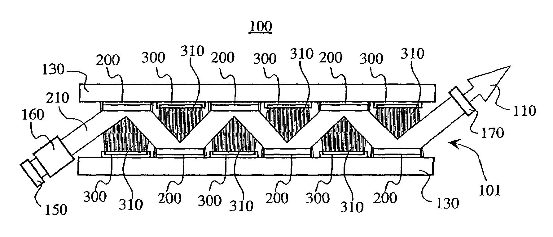
[0018]An embodiment of the present invention provides a multiple
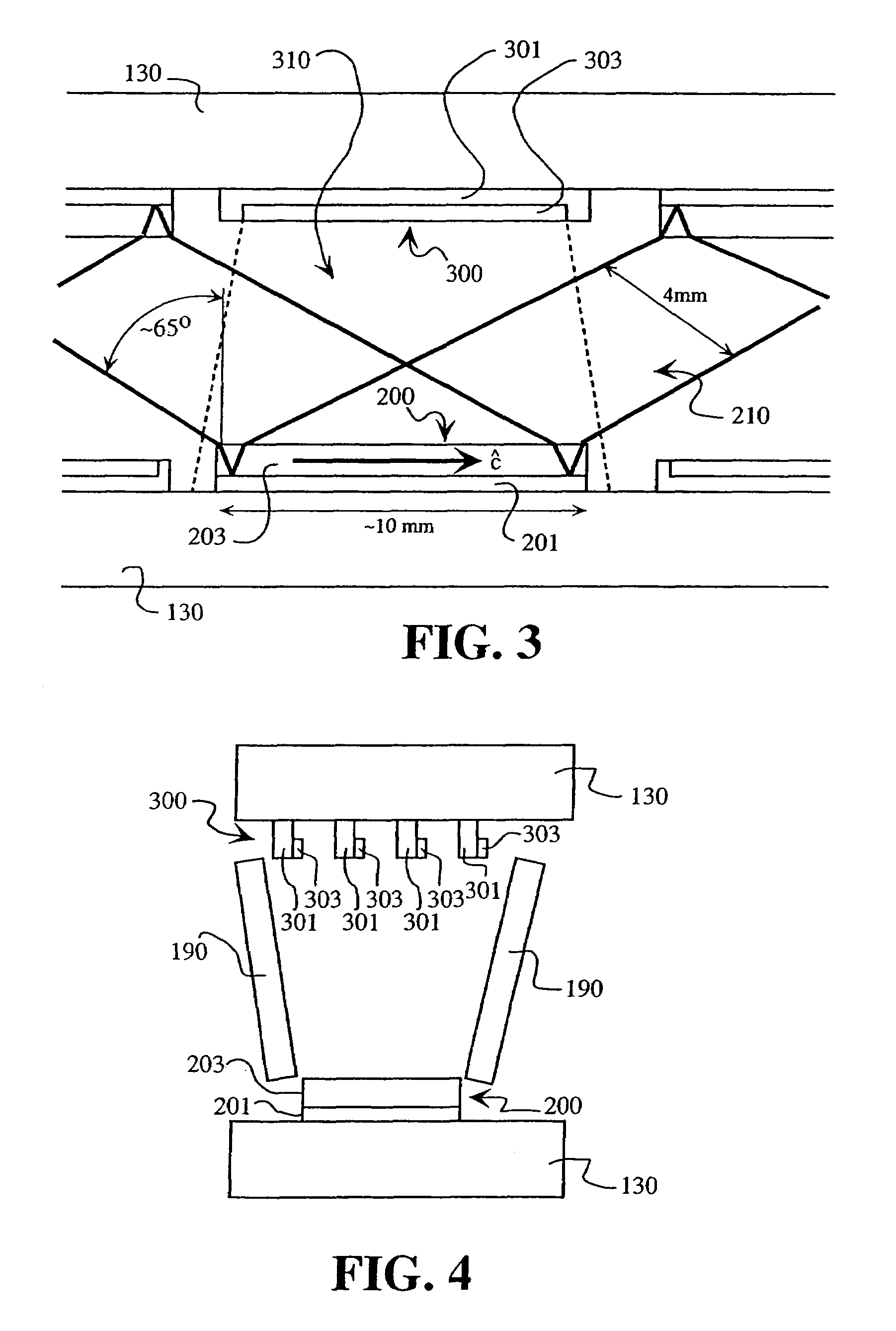
disk laser system for producing a laser beam, the laser system having top and bottom heat-sinking bars forming the structure of the laser system. A plurality of disks comprising a laser material is mounted on both the top surface of the bottom heat-sinking bar and the bottom surface of the top heat-sinking bar. Also mounted on both heat-sinking bars is a plurality of pump diode bars. Each pump diode bar is preferably mounted opposite a corresponding laser disk on the opposite heat-sinking bar. Preferably, the pump diode bars and the disks are symmetrically mounted on the top and bottom heat-sinking bars, so that each heat-sinking bar has an alternating pattern of pump diode bars and laser disks. The laser system is preferably configured such that the lasing or extracting beams impinge on the disks with an incidence angle far off normal, preferably with an incidence angle near Brewster's angle for the laser material used. In a preferred embodiment, the laser material is Nd:YVO4 and the number of disks used in the system is preferably an even number.
[0019]In accordance with the present invention, the
parasitic oscillation problem is addressed by using enough disks (typically, two or more disks) so that the total
optical path length through the disks is greater than the transverse
path length within a single disk. Having the highest
gain along the path taken by the
optical beam tends to reduce
parasitic oscillation transverse to the
optical path. This allows the use of larger disks than those typically used in laser systems having multiple disks, such as the apparatus disclosed in Hügel, discussed above.
[0020]Further, in accordance with the present invention, the extracting beams are purposely directed at the disks with a far from normal incidence, whereas in conventional disk lasers, the goal is to direct the extracting beams with near normal incidence on the disks. Having an
angle of incidence far from normal goes against conventional wisdom in the art of
disk laser design. This is because when the beam path is no longer parallel to the thermal gradients,
thermal distortion of the
optical beam occurs. To compensate for this
thermal distortion, embodiments of the present invention preferably use an even number of disks, so that alternating bounces compensate for the thermal distortions. This is similar to the thermal compensation seen in prior art laser systems using a zig-zag slab geometry, that is, where the lasing beam propagates within a slab of laser material in a zig-zag manner. An additional
advantage of having the extracting beam far from normal incidence, is that more space is made available opposite the disks, thus allowing pump diodes to be positioned closer to the disks. Therefore, the pumping geometry of embodiments of the present invention is generally simpler than the geometries used in prior art systems, such as the geometry of the Inazuma Periodic
Resonator discussed above.
[0021]Additionally, in a preferred embodiment of this invention, Nd:YVO4 is used as the laser material. Although Nd:YVO4 has poorer thermal and mechanical properties than Nd:YAG crystals, for example, it has a much higher laser cross section (and therefore higher
gain). The parasitic oscillation resulting from the higher gain is dealt with by using multiple disks. Hence, embodiments of the present invention may use much larger disks than those typically used in prior art laser systems. Further, embodiments of the present invention make use of the
anisotropy of Nd:YVO4 in order to minimize parasitic oscillations and losses.
[0022]In accordance with the present invention, the incidence of the extracting optical beam is off-normal. For any given disk, the aberrations resulting from off-normal incidence of the extracting beam, are compensated by a nearby disk. Under these conditions, the extracting optical
beam angle of incidence may be as large as Brewster's angle, where the Fresnel
reflection loss is near zero for one polarization.

