Digital transmitter and method

Active Publication Date: 2006-01-17
MICROSOFT TECH LICENSING LLC
View PDF12 Cites 40 Cited by
  • Summary
  • Abstract
  • Description
  • Claims
  • Application Information

AI Technical Summary

Problems solved by technology

Component variation, tolerances, and aging all affect the design requirements, costs, and manu

Method used


Image

  • Digital transmitter and method
  • Digital transmitter and method
  • Digital transmitter and method

Examples


Embodiment Construction

Digital Transmitter

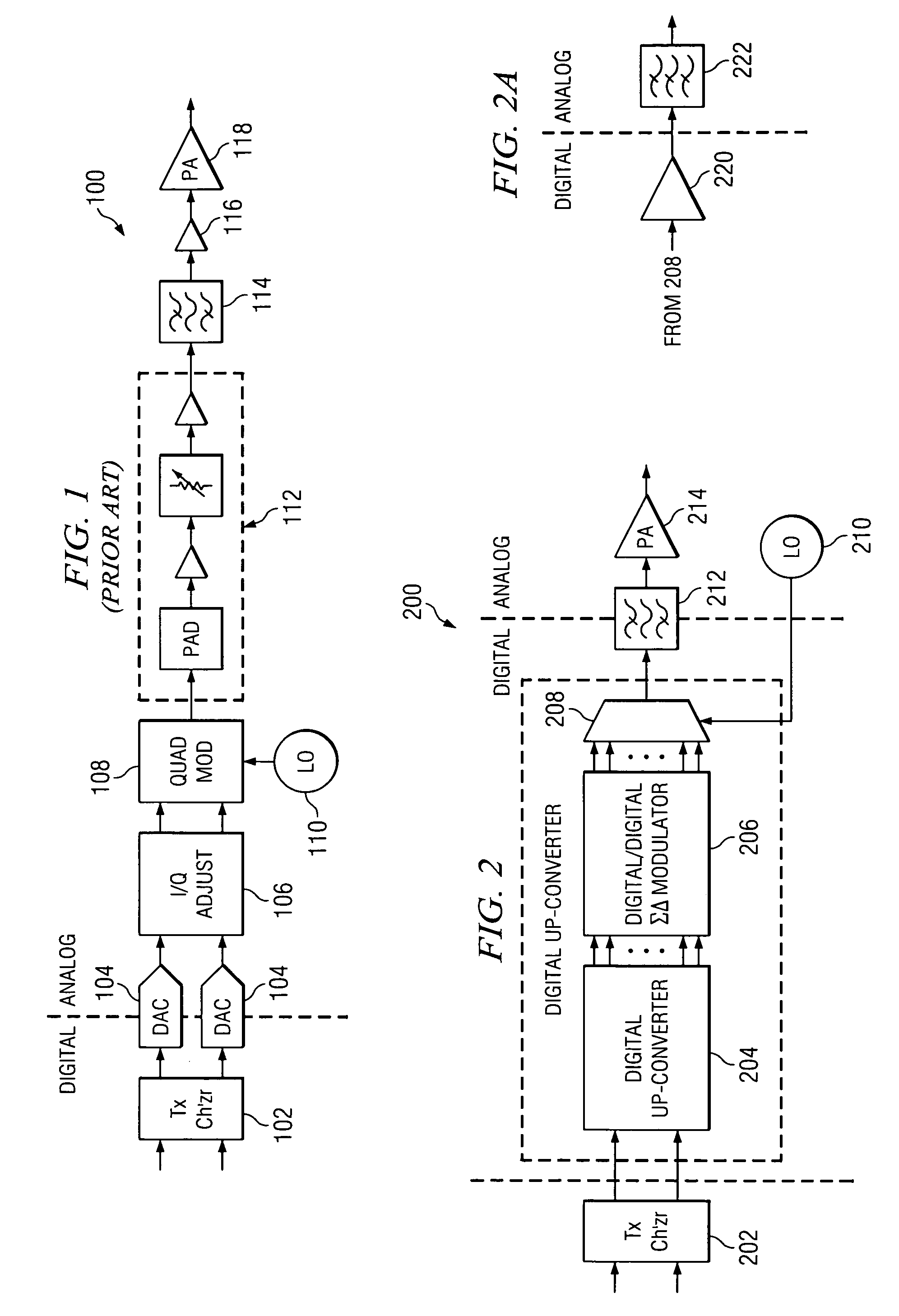
[0023]With reference to FIG. 1, there is shown a relevant portion of a prior art analog transmitter 100 of the type used in conventional digital communications systems. The transmitter 100 includes a transmit channelizer 102 receiving coded I and Q digital baseband signal inputs. The I and Q digital inputs each typically comprise a stream of samples (or chips) representing a digital value, or word having n bits. The sample rate (or chip rate) of the I and Q inputs to the channelizer 102 is determined in accordance with the technology and / or standard utilized (e.g., CDMA(IS-95) is 1.2288 Mcps, UMTS is 3.84 Mcps, etc.).

[0024]As will be appreciated, the processing, generation and functionality utilized to generate the I and Q digital signals that are input to the channelizer 102 are not shown or described. This is known to those of ordinary skill in the art. In general terms, the digital data is processed by encoding, interleaving, converting, and spreading (using or...


PUM


Abstract

A transmitter and method is provided for digitally upconverting a baseband digital signal to a modulated intermediate frequency (IF) digital signal and sigma-delta modulating the IF digital signal. The baseband digital signal is split into N phases, as can be accomplished using a polyphase interpolation technique (polyphase filter), and modulated. The modulated N phases are not recombined and each phase is further modulated, as can be accomplished using a digital-to-digital sigma-delta modulator that generates digital output signals at the same rate. A high speed digital multiplexer multiplexes the digital output signals into a single bit stream at a higher rate for subsequent power amplification and RF transmission.

Description

CROSS REFERENCE TO RELATED APPLICATION(S)[0001]This application is related to another commonly owned United States patent application entitled “DIGITAL RECEIVER AND METHOD” filed concurrently herewith, Ser. No. 10 / 403,633, and which is incorporated herein by reference.TECHNICAL FIELD OF THE INVENTION[0002]The present invention relates to transmitters, in particular, to a digital transmitter for use in communications.BACKGROUND[0003]In current digital wireless systems, the traditional up-conversion chain (or significant portion thereof) is primarily analog and includes types such as super-heterodyne, low intermediate frequency (IF) and zero IF up-conversion technology. These technologies start with the conversion of inherently digital signals to analog signals through high performance digital-to-analog (D / A) converters, generally due to the higher frequencies involved. Once converted to the analog domain, various combinations of analog filters, amplifiers, mixers and modulators (and ...

Claims


Application Information

Patent Timeline
IPC IPC(8): H04B1/02H04B1/04
CPCH04B1/0483
Inventor MORRIS, BRADLEY JOHNFULLER, ARTHUR THOMAS GERALD
Owner MICROSOFT TECH LICENSING LLC
Why Eureka
Try Eureka