External transformer correction in an electricity meter

a transformer and electricity meter technology, applied in the field of electric meters, can solve problems such as raw data errors

Inactive Publication Date: 2006-01-17
LANDIS GYR LLC
View PDF3 Cites 85 Cited by
  • Summary
  • Abstract
  • Description
  • Claims
  • Application Information

AI Technical Summary

Benefits of technology

[0016]The present invention fulfills the above need, as well as others, by providing a meter that stores information representative of error ratings of an external transformer, and then adjusts energy consumption values based at least in part on the stored information. Because the energy consumption values are adjusted based on the stored information representative of the error ratings of an external transformer, the meter can adjust the its energy consumption calculations to compensate for errors caused by the external transformer.
[0021]The above described method provides an advantage in that the amount of the adjustment is dynamic, and changes as the level of power consumed changes. As a result, the meter can compensate for an error of the transformer that varies as a function of the power (or current) through the transformer. This advantage can increase metering accuracy, regardless of whether the compensation is applied to the voltage and / or current samples or the final energy consumption calculations.

Problems solved by technology

By contrast, systems that adjust the watt-hour calculations alone may still use the erroneous raw data for other types of calculations within the meter.

Method used


Image

  • External transformer correction in an electricity meter
  • External transformer correction in an electricity meter
  • External transformer correction in an electricity meter

Examples


Embodiment Construction

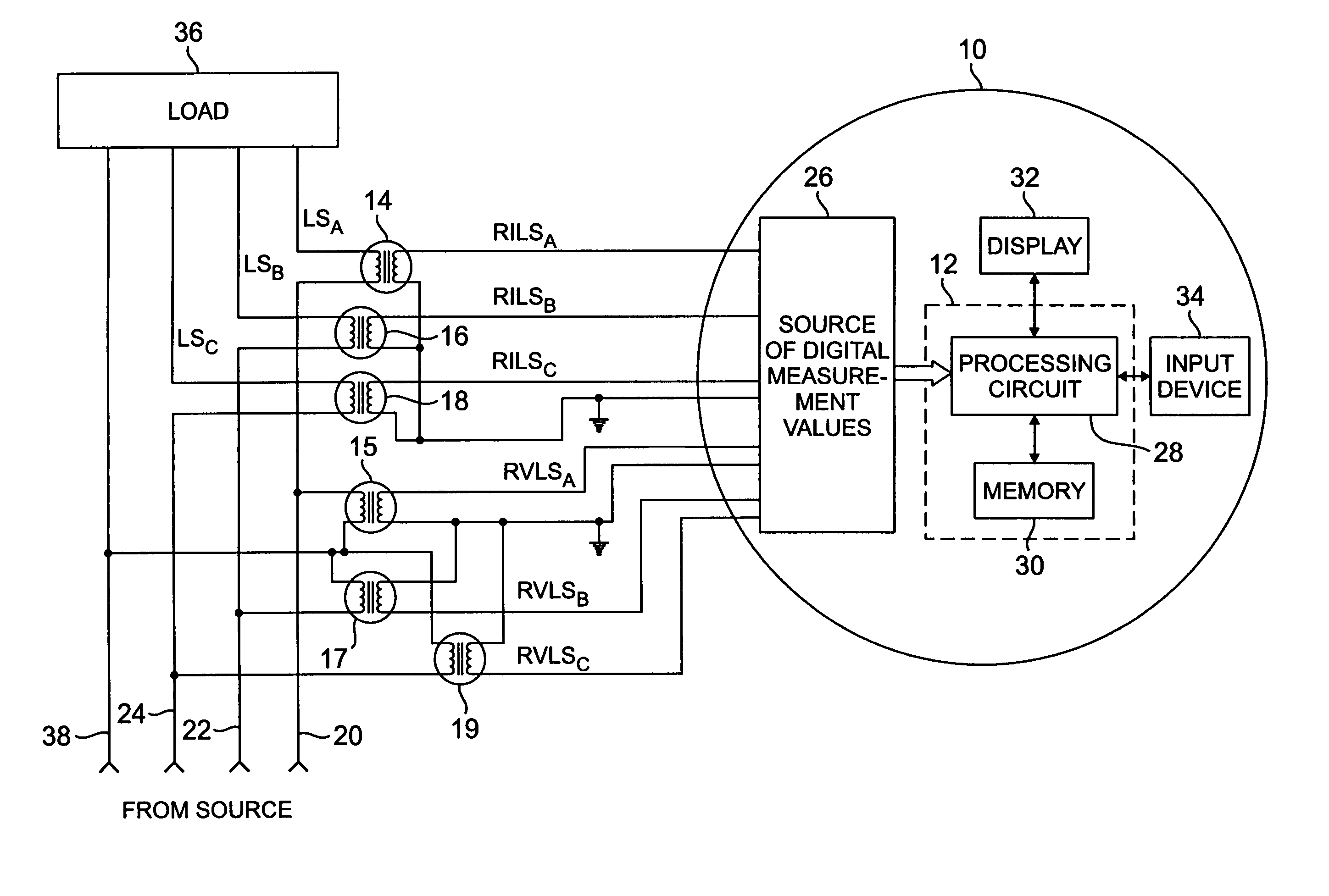
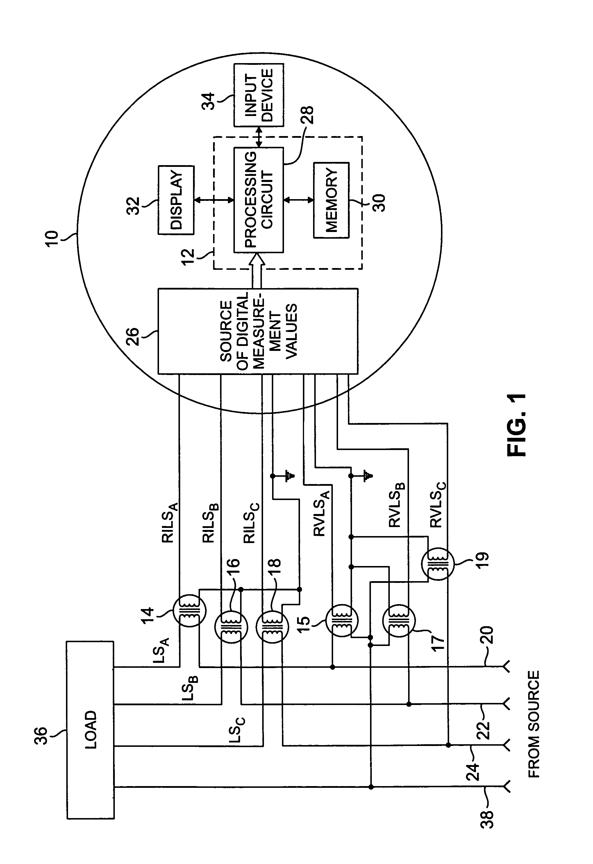
[0030]FIG. 1 shows a schematic block diagram of an exemplary electricity meter 10 that incorporates a compensation apparatus 12 according to the present invention. The electricity meter 10 is shown in context installed in a three phase power system. The exemplary embodiment of the compensation apparatus 12 described herein compensates for measurement errors caused by three external current transformers (“CTs”) 14, 16, and 18, and three external potential transformers (“PTs”) 15, 17 and 19. The CTs 14, 16 and 18 and the PTs 15, 17 and 19, respectively cooperate to couple the electricity meter 10 to the three phase power lines 20, 22, and 24, respectively.

[0031]While the electricity meter 10 in FIG. 1 is configured to measure a three phase, four wire wye service connection as is known in the art, it is be appreciated that those of ordinary skill in the art may readily modify the arrangement of FIG. 1 to accommodate a three wire delta, four wire delta, or other standard service connect...


PUM


Abstract

A method compensates for measurement errors of an external transformer coupled between an electricity meter and one or more power lines. The method includes a first step of obtaining at least one error rating for the external transformer. The method also includes the step of storing data representative of the at least one error rating in a memory within the meter. At some point the electricity meter is coupled to the external transformer. The method further includes the step of employing the meter to obtain at least one electricity consumption measurement value, the at least one electricity consumption value including either a sampled current value or a sampled voltage value. Finally, the method includes the step of causing the meter to adjust the at least one electricity consumption measurement value using at least a portion of the stored data.

Description

[0001]This application claims the benefit of U.S. Provisional Patent Application No. 60 / 160,675, filed Oct. 21, 1999.FIELD OF THE INVENTION[0002]The present invention relates generally to electricity meters, and in particular, to electricity meters that are coupled to a system to be measured via external transformers.BACKGROUND OF THE INVENTION[0003]Electricity meters are devices that, among other things, measure the consumption of electricity by a residence, factory, commercial establishment or other such facility. Electricity meters may also be employed to measure electricity flow between different electrical power generation or delivery systems. Electrical utility service providers employ electricity meters to track customer usage of electrical power or energy. Utilities track customer usage for many purposes, including billing and tracking demand.[0004]At present electricity meters often include digital circuitry that performs many of the energy-related calculations. Examples of...

Claims


Application Information

Patent Timeline
Patent Type & Authority Patents(United States)
IPC IPC(8): G01R21/00G01R35/04
CPCG01R35/04
Inventor RANDALL, BRUCE E.
Owner LANDIS GYR LLC
Why Eureka
Try Eureka