Leaf collection system for a lawn blower/vacuum

a collection system and vacuum technology, applied in the direction of cleaning filter means, turf growing, separation processes, etc., can solve the problems of annoying dust expulsion from cloth bags, and the need to transfer leaves collected in the collection bags to another container for disposal, so as to save labor.

Inactive Publication Date: 2006-01-24
RITTER JOSEPH K
View PDF8 Cites 40 Cited by
  • Summary
  • Abstract
  • Description
  • Claims
  • Application Information

AI Technical Summary

Benefits of technology

[0004]The leaf collection system of this invention provides an environmentally friendly and labor saving alternative to conventional collection bags for conventional lawn blower / vacuums. The apparatus of the leaf collection system includes a port coupling, a dust cover, and a unique disposable collection bag. The port coupling mates to the side port of blower / vacuum and has a plurality of nubs that protrude radially around the distal end of the coupling. The disposable collection bag is constructed of an environmentally friendly, bio-degradeable plastic that will quickly decompose along with the organic leaves and lawn debris collected therein. Both sides of the collection bag have several rows of T-shaped slits and two rows of straight or I-shaped slits that allow air to escape from the bag but retain the leaves and lawn debris deposited therein. The collection bag is shaped to fit inside the dust cover that is fixed to the port coupling. The dust cover envelops the collection bag and shields the operator from the dust that passes through the collection bag.

Problems solved by technology

While the cloth collection bags retain most of the leaves and debris, annoying dust is expelled from the cloth bags.
Consequently, operators often need masks and goggles to operate the blower / vacuum and even with such protection, the operator is generally covered in the dust from the collection bag.
Another drawback of the conventional blower / vacuums is that the leaves collected in the collection bag must be transferred to another container for disposal.

Method used


Image

  • Leaf collection system for a lawn blower/vacuum
  • Leaf collection system for a lawn blower/vacuum
  • Leaf collection system for a lawn blower/vacuum

Examples


Embodiment Construction

[0015]The preferred embodiment herein described is not intended to be exhaustive or to limit the invention to the precise form disclosed. It is chosen and described to best explain the invention so that others skilled in the art might utilize its teachings.

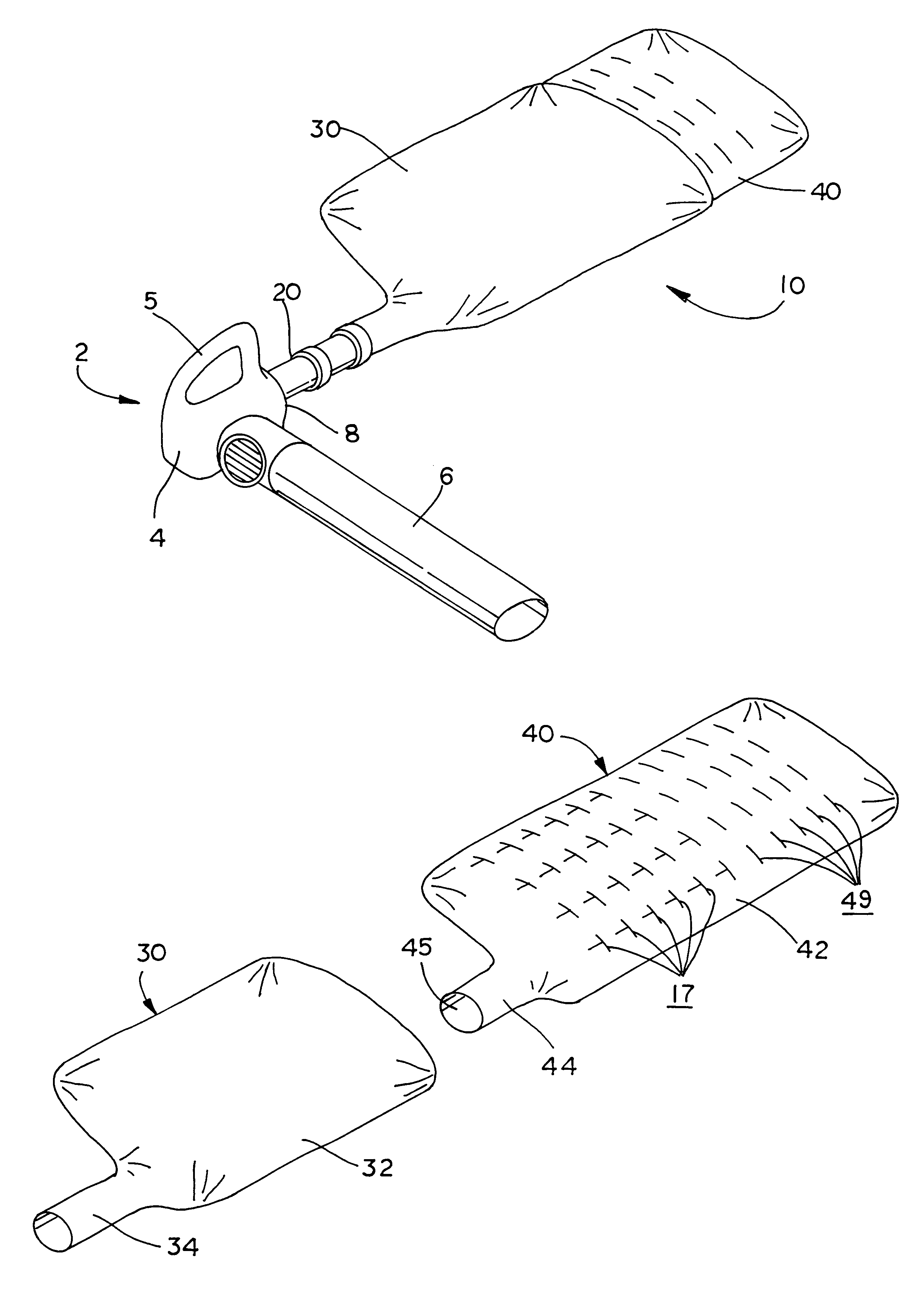
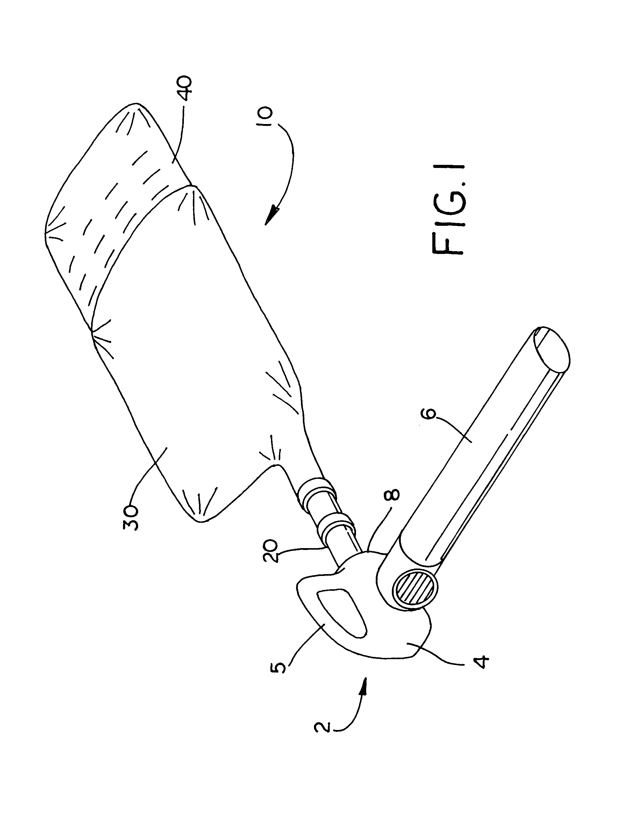
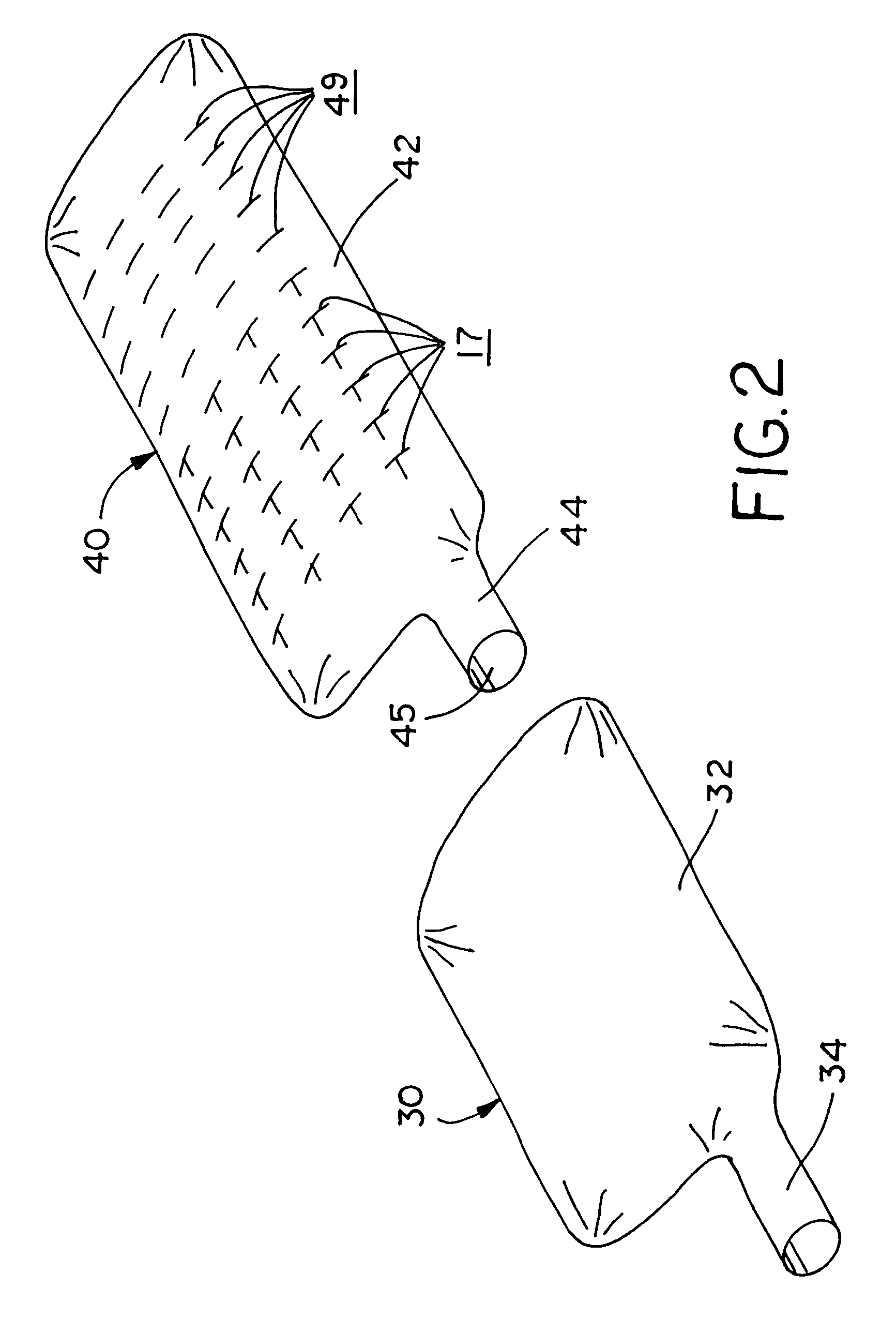
[0016]In the figures, the apparatus of the collection system of this invention is designated generally as reference numeral 10 and the blower / vacuum is designated generally as reference numeral 2. Blower / vacuum 2 is illustrated as having a conventional design that uses a bladed fan that generates both the positive pressure air flow and the negative pressure vacuum. The bladed fan is driven by either an electric or gas motor (not shown). The motor and fan are enclosed in a housing 4 that includes a handle 5. A long nozzle 6 and a side port 8 extend from housing 4. In the blower mode, the fan draws air in through side port 8 and expels it through nozzle 6. In a suction mode, the fan draws leaves and debris through nozzle 6 and expel...


PUM

PropertyMeasurementUnit
air flow rateaaaaaaaaaa
vacuumaaaaaaaaaa
timeaaaaaaaaaa

Abstract

A leaf collection system for lawn blower/vacuums is disclosed. The collection system includes a port coupling fitted to the exhaust port of a blower/vacuum, a dust cover, and a unique disposable collection bag. The disposable collection bag is constructed of an environmentally friendly, bio-degradeable plastic that will quickly decompose along with the organic leaves and lawn debris collected therein. Both sides of the collection bag has several rows of T-shaped slits and two rows of straight or I-shaped slits that allow air to escape from the bag but retain the leaves and lawn debris deposited therein. The collection bag is shaped to fit inside the dust cover that is fixed to the port coupling. The port coupling includes an elastic lock ring that secures the collection bag to the coupling. The dust cover envelops of the collection bag and shields the operator from the dust that passes through the collection bag.

Description

[0001]This invention relates to lawn blower / vacuums and in particular, a leaf collection system with disposable collection bags for a lawn blower / vacuum.BACKGROUND OF THE INVENTION[0002]Lawn blower / vacuums have become a convenient lawn care tool. Blower / vacuums are particularly valuable in the fall season for leaf collection and constitute a significant improvement over the common lawn rake for leaf collection. Blowers are commonly used to blow the leaves into piles for collection. Conventional blower also include a vacuum feature that can vacuum leaves in a collection bag. The blower / vacuum can be switched to blow the leaves into a pile, then switched to vacuum the leaves into a collection bag. Conventional blower / vacuums use an electric or gas motor that propels a bladed fan that generates the stream of air to blow the fallen leaves or the vacuum force to collect the lawn debris.[0003]Heretofore, the conventional collection bags have been heavy cloth sacks attached to the exhaust ...

Claims


Application Information

Patent Timeline
Patent Type & Authority Patents(United States)
IPC IPC(8): A47L9/10E01H1/08A01G1/12A47L5/14A47L9/14
CPCA01G1/125A47L9/14A47L5/14Y10S55/02A01G20/47
Inventor RITTER, JOSEPH K.
Owner RITTER JOSEPH K
Why Eureka
Try Eureka