Valve system and method for unheading a coke drum

a coke drum and valve system technology, applied in the direction of coke oven details, wing accessories, charging-distribution device combinations, etc., can solve the problems of coke being slashed from the valve and otherwise breaking the connection or attachment of the valve closure, and achieve the effect of simplifying the decoking process

Inactive Publication Date: 2006-01-24
DELTAVALVE
View PDF28 Cites 43 Cited by
  • Summary
  • Abstract
  • Description
  • Claims
  • Application Information

AI Technical Summary

Benefits of technology

[0020]An advantage of the present invention is its ability to provide a simple, yet effective de-heading system comprising a de-header valve having a movable valve closure that oscillates or moves back and forth about the means for supporting the valve closure to de-head a coke drum and simplify the decoking process. Another advantage of the present invention is the ability to de-head the coke drum without having to physically remove the head or flange unit, and to do so at a remote location with little or no manual requirements. Other advantages will be apparent to one skilled in the art.
[0021]In a preferred embodiment, the means for supporting the valve closure comprises a seat support system. The seat support system may comprise any arrangement or configuration of seats, depending upon the type of valve, the needs of the system, system specifications, or any other contributing factors. In one exemplary configuration, the seat support system comprises an upper and lower seat existing on either side of the valve closure, wherein the upper seat and lower seat may be independent from one another. Still further, the upper and lower seat may be comprised of either a static or dynamic nature, such that one may be static and the other dynamic, both dynamic, or both static.
[0022]In another exemplary embodiment, the seat support system comprises a single seat situated or disposed between the main body of the de-header valve and the valve closure. In this configuration, the single seat applies a continuous force to the valve closure throughout its oscillation. The single seat may be a floating or dynamic seat, or it may be a static seat, again depending upon the type of valve, the needs of the system, system specifications, or any other contributing factors.
[0023]In several embodiments, the biasing necessary to maintain bug term sealing is provided by the gate itself. Several gates are biased against the seat to provide the same contact that would occur if the seat were biased toward the gate.
[0024]In a preferred embodiment, the seat support system advantageously provides a floating seat concept to the de-header valve using at least one dynamic, live loaded seat. This floating dynamic, live loaded seat is continuously loaded against the valve closure to create a biased relationship between the seat(s) and the valve closure. The floating seat concept is accomplished using one or a combination of biasing members, such as heavy coil springs arrayed at close centers around the perimeter of the seat ring; externally live loaded and sealed seat force applicators arrayed at quadrants around the floating seats; and / or a full perimeter flexible inconnel bellow seal spring placed between the floating seat and the seat retaining ring. One embodiment of the present invention utilizes a floating two piece gate to provide a floating seal with a static seat. The tow plates that form the gate are biased away from each other to seal against the seat. A floating or dynamic seat or gate provides many advantages, a primary one being that the seat support system and the valve closure are able to flex and distort in response to the rigorous and changing pressures and forces induced thereon during the coke manufacturing process and filling of the coke drum.
[0025]In another exemplary embodiment, means for supporting the valve closure comprises the main body itself. In this embodiment, no seats are required as various structural modifications can be made to the main body to support the valve closure. However, it is contemplated that a seat may be used to support the valve closure on one side and the main body on the other.

Problems solved by technology

As the valve closure is caused to move, its metal surface slides about the metal surface of the means for supporting the valve closure, thus shearing the coke from and otherwise breaking its connection or attachment with the valve closure.

Method used


Image

  • Valve system and method for unheading a coke drum
  • Valve system and method for unheading a coke drum
  • Valve system and method for unheading a coke drum

Examples


Embodiment Construction

[0066]It will be readily understood that the components of the present invention, as generally described and illustrated in the figures herein, could be arranged and designed in a wide variety of different configurations. Thus, the following more detailed description of the embodiments of the system, device, and method of the present invention, as represented in FIGS. 1 through 20, is not intended to limit the scope of the invention, as claimed, but is merely representative of the presently preferred embodiments of the invention.

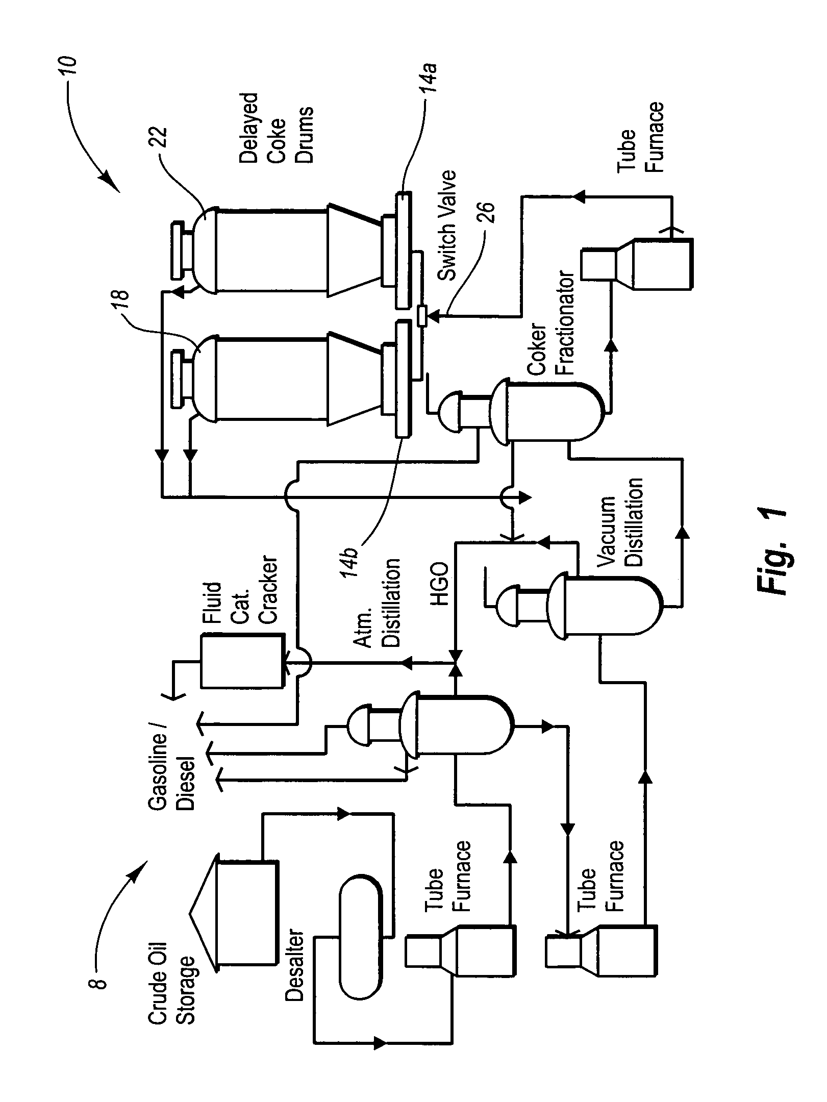
[0067]The presently preferred embodiments of the invention will be best understood by reference to the drawings wherein like parts are designated by like numerals throughout. Although reference to the drawings and a corresponding discussion follow below, the following more detailed description is divided into sections. The first section pertains to and sets forth a general discussion of the delayed coking process, including the process and effects of de-head...


PUM

PropertyMeasurementUnit
thermal cracking temperaturesaaaaaaaaaa
heightaaaaaaaaaa
heightaaaaaaaaaa

Abstract

The present invention features systems and methods for de-heading a coke drum without having to physically remove the head units. This is accomplished using a de-header valves that may be removably coupled to a coke drum. The de-header valve is equipped with, a valve closure and a seat support system capable of forming a continuous contact seal during the coke manufacturing process. Actuation of the valve closure functions to open and close the de-header valve. Once the drum is full, the de-header valve may be actuated (opened), wherein the coke that has accumulated on the blind is sheared by the seat support system, thus effectively de-heading the coke drum and facilitating the decoking process.

Description

RELATED APPLICATIONS[0001]This application is a continuation of U.S. patent application Ser. No. 10 / 731,874, filed Dec. 9, 2003, entitled, “Valve System and Method for Unheading Coke Drum,” and to U.S. patent application Ser. No. 10 / 096,301, filed Mar. 11, 2002, entitled, “Coke Drum Bottom De-Heading System,” now issued as U.S. Pat. No. 6,660,131; and to U.S. patent application Ser. No. 09 / 946,917, filed Sep. 5, 2001, entitled, “Coke Drum Bottom De-Heading System,” now issued U.S. Pat. No. 6,565,714, which claims priority to U.S. Provisional Patent Application Ser. No. 60 / 275,527, filed Mar. 12, 2001, entitled, “Coke Drum Bottom De-Heading System.” Each of these related applications is incorporated by reference herein in their entirety.BACKGROUND[0002]1. Field of the Invention[0003]The present invention relates to the devices and systems used to de-head or unhead a vessel containing a fluid, distillate, or unconsolidated debris byproduct produced from a manufacturing process, such a...

Claims


Application Information

Patent Timeline
Patent Type & Authority Patents(United States)
IPC IPC(8): C10B25/00C10B25/22C10B25/20C10B25/10F16K3/14F16K3/20
CPCC10B25/10F16K3/205F16K3/14
Inventor LAH, RUBEN F.
Owner DELTAVALVE
Why Eureka
Try Eureka