Flatness correction

Active Publication Date: 2006-01-24
NATIONAL INSTRUMENTS
View PDF12 Cites 2 Cited by
  • Summary
  • Abstract
  • Description
  • Claims
  • Application Information

AI Technical Summary

Benefits of technology

[0009]The calibration process operates to create a digital filter for a measurement device. The measurement device may include a plurality of channels and each channel may have one or more channel modes, such as AC or DC coupling mode and voltage ranges, such as 0–5 V, ±5 V, and ±50 mV, among others. The measurement device is operable to measure signals in a desired frequency range. Due to physical limitations of the analog interface circuitry of the measurement device, the gain of each channel on the measurement device may be attenuated and/or may be non-linear in the desired frequency range. The calibration process generates filter coefficients for a plurality of channel and mode combinations. The filter coefficients are used by a digital filter, which is operable to compensate for the non-linearlity in the desired frequency range. The calibration process may be implemented during manufacturing of the measurement device.
[0010]The measurement device such as a DMM may include four basic units—an analog circuit path, an analog to digital converter (ADC), the digital filter, and an RMS computation unit. The four basic units may be operable to multiplex or to process one or more of the plurality of channels at the same time. The analog circuit path may include the necessary circuitry for the plurality of channels to couple to one or more analog signals. The analog circuit path may include one or more of an analog interface, analog signal conditioning, voltage isolation units, multiplexers, and analog filters, besides others. The analog circuit path may couple to the ADC. Th

Problems solved by technology

Due to physical limitations of the analog interface circuitry of the measurement device, the gain of each c

Method used


Image

  • Flatness correction
  • Flatness correction
  • Flatness correction

Examples


Example

DETAILED DESCRIPTION OF THE FIGURES

FIG. 2—Computer System Block Diagram

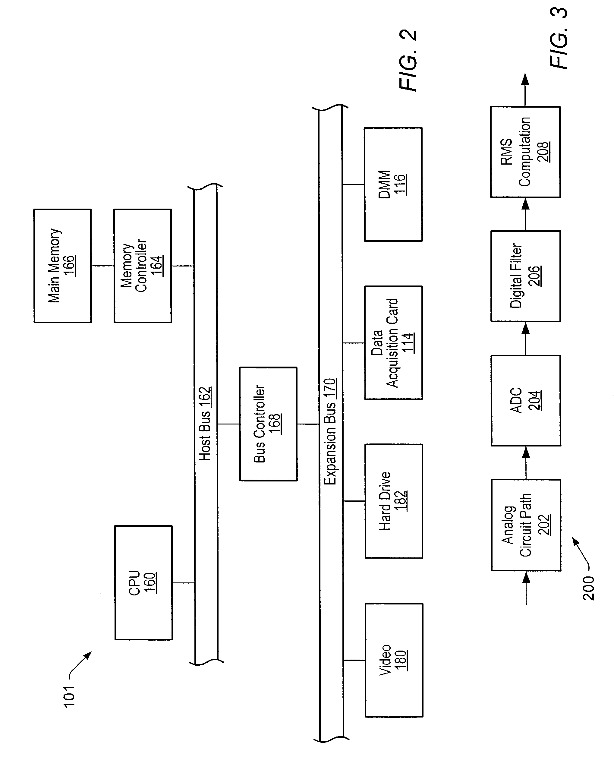
[0021]FIG. 2 is a block diagram representing one embodiment of a computer system 101. It is noted that any type of computer system configuration or architecture can be used as desired, and FIG. 2 illustrates a representative PC embodiment. It is also noted that the computer system may be a general purpose computer system, a computer implemented on a VXI card installed in a VXI chassis, a computer implemented on a PXI card installed in a PXI chassis, or other types of embodiments. Elements of a computer not necessary to understand the present description have been omitted for simplicity.

[0022]The computer may include at least one central processing unit or CPU 160 which is coupled to a processor or host bus 162. The CPU 160 may be any of various types, including an x86 processor, e.g., a Pentium class, a PowerPC processor, a CPU from the SPARC family of RISC processors, as well as others. Main memory 166 may be co...


PUM


Abstract

A calibration system for measurement device is operable to calibrate each channel response to compensate its own gain error for a desired frequency range. The channel modes may include voltage range and a coupling mode. Each channel of the plurality of channels may have a certain number of channel mode combinations, including different voltage ranges and coupling modes. Each channel also may have a different frequency response, and as a result each channel mode combination may require an individual digital filter. As a result, the frequency response of each channel may be characterized and the digital filter may be designed to flatten each channel mode combination. The designed filter coefficients for each of the one or more channels of the plurality of channels may be stored in the measurement device. The filter coefficients may be used by a digital filter in order to compensate each one of the one or more channels on the measurement device. The calibration process may be implemented during manufacturing of the measurement device.

Description

PRIORITY CLAIM[0001]This application claims benefit of priority of U.S. provisional application Ser. No. 60 / 403,303 titled “Flatness Correction” filed Aug. 14, 2002, whose inventor was James Nagle.FIELD OF THE INVENTION[0002]The present invention relates to the field of computer-based test systems, and more particularly to a system and method for correcting frequency response of a digital multi-meter.DESCRIPTION OF RELATED ART[0003]A digital multi-meter, herein referred to as a DMM, is a type of a measurement device, i.e., a piece of test equipment, used to measure voltage, current, resistance, and possibly other analog and / or digital electrical phenomena. Most DMM's are also operable to display a value of the measurement. A typical DMM may include a plurality of channels, and may be operable to measure DC voltage, AC voltage (RMS value), and resistance (ohms), besides others.[0004]Each of the plurality of channels may be operable to measure a signal at a range of frequencies. For e...

Claims


Application Information

Patent Timeline
IPC IPC(8): G01R23/167G01R1/38G01R35/00
CPCG01R35/005
Inventor NAGLE, JAMES
Owner NATIONAL INSTRUMENTS
Why Eureka
Try Eureka