
Power supply apparatus and electric vehicle using the same

a technology of power supply apparatus and electric vehicle, which is applied in the direction of hybrid vehicles, electric generator control, electric devices, etc., can solve the problems of high breakdown voltage and breakdown current required to the resistor, high resistor and switch price, and rise in the manufacturing cost of the power supply apparatus, etc., and achieves the effect of simple circuit structur

Inactive Publication Date: 2005-08-02
HONDA MOTOR CO LTD
View PDF19 Cites 96 Cited by
  • Summary
  • Abstract
  • Description
  • Claims
  • Application Information

AI Technical Summary

Benefits of technology

The present invention provides a power supply apparatus for vehicles or automobiles using a power supply system with a simple circuit structure. The apparatus includes a first battery unit for a higher voltage, a second battery unit for a lower voltage, a smoothing condenser, a DC-DC converter, and an electronic control unit. The electronic control unit controls the DC-DC converter to charge the smoothing condenser from the second battery unit in an initial precharging state prior to the steady state. The apparatus also allows for a smooth charging operation and detects and addresses faults during the initial charging operation. The technical effects of the invention include improved power supply efficiency, reduced charging time, and improved reliability and stability of the power supply system.

Problems solved by technology

Because large current flows through the resistor and the switch in the high voltage, a high breakdown voltage and a breakdown current are required to the resistor and the switch.
As a result, the resistor and the switch become expensive and the manufacturing cost of the power supply apparatus rises.

Method used


Image

  • Power supply apparatus and electric vehicle using the same
  • Power supply apparatus and electric vehicle using the same
  • Power supply apparatus and electric vehicle using the same

Examples


first embodiment

(First Embodiment)

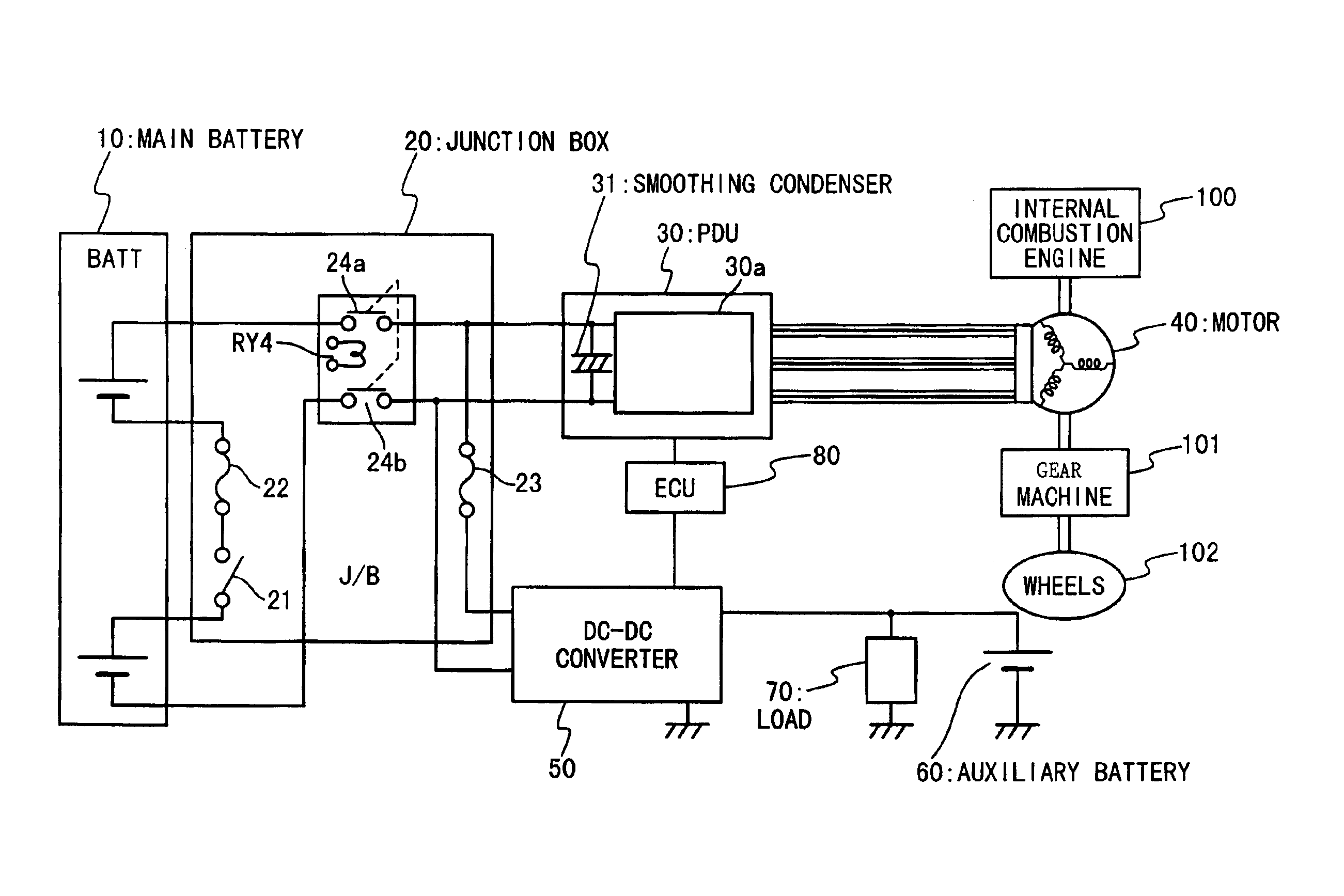
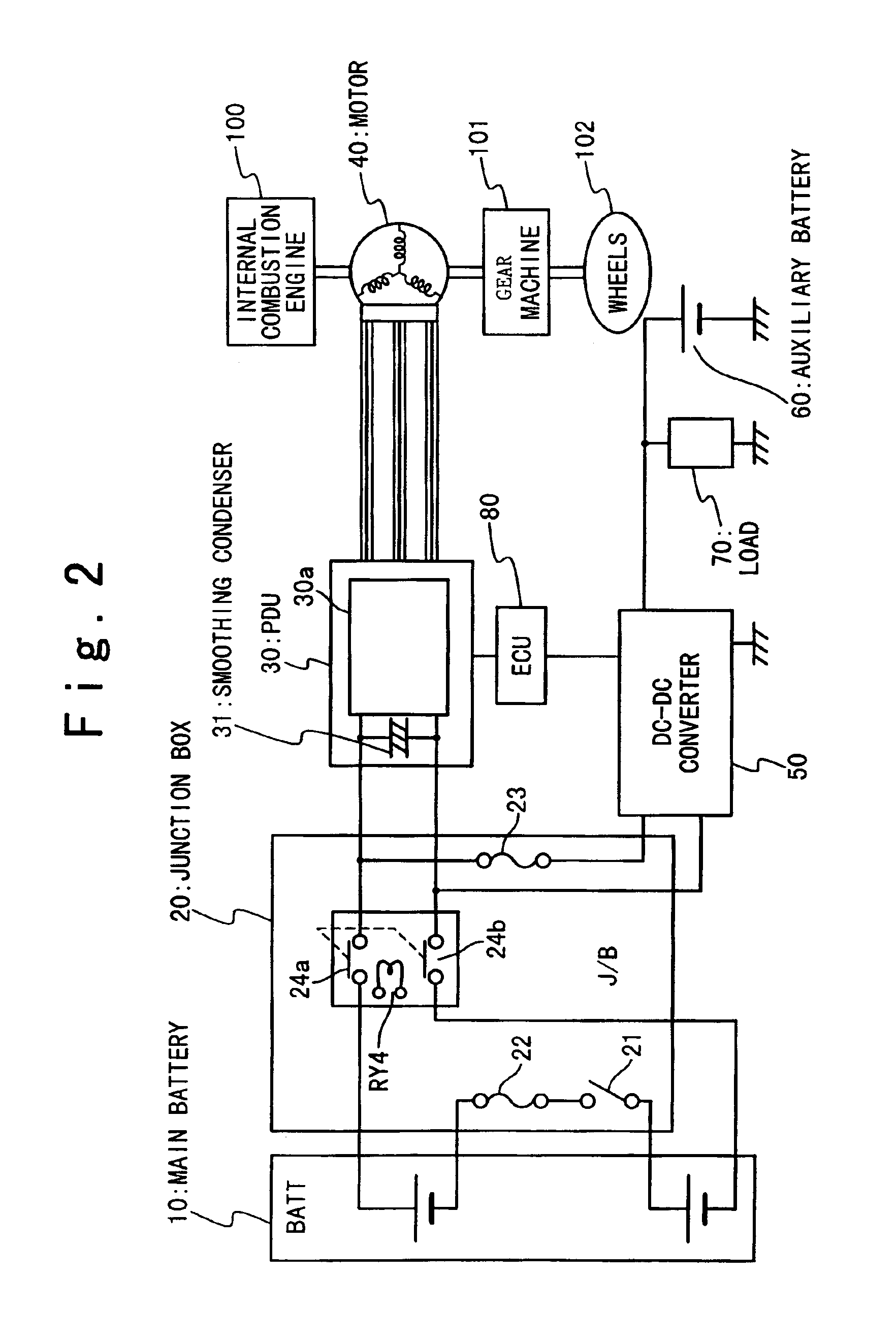
[0063]FIG. 2 is a block diagram showing the circuit structure of the vehicle using the power supply apparatus according to the first embodiment of the present invention. FIG. 8 shows the simplified circuit structure of it. Referring to FIGS. 2 and 8, the vehicle using the power supply apparatus is comprised of a main battery (BATT) 10 as a first power unit, a junction box (J / B) 20, a power drive unit (PDU) 30 with a smoothing condenser 31, a motor 40, a DC-DC converter 50, an auxiliary battery 60 as a second power unit, a load 70 and an electronic control unit (ECU) 80. The motor 40 is coupled to a crankshaft between an internal combustion engine 100 and a gear machine 101, and wheels 102 are connected to the gear machine 101.

[0064]The main battery 10 outputs the DC power of as high voltage as 144 V. The power outputted from the main battery 10 is supplied to the power drive unit 30 and the DC-DC converter 50 via the junction box 20.

[0065]The junction box 20 accomm...

second embodiment

(Second Embodiment)

[0094]Next, the vehicle using the power supply apparatus according to the second embodiment of the present invention will be described. The power supply apparatus according to the second embodiment controls the output of the DC-DC converter variably and detects of a fault in the initial charging operation.

[0095]FIG. 9 is a block diagram showing the circuit structure of the power supply apparatus according to the second embodiment of the present invention. The circuit structure of the power supply apparatus according to the second embodiment is the same as the power supply apparatus according to the first embodiment shown in FIG. 8 except that a battery current sensor 12 is added.

[0096]In the initial charging operation in the conventional power supply apparatus, the initial charging time is principally determined based on the resistance of the resistor 25, the voltage of the main battery 10, the capacity of the smoothing condenser 31 and so on. Therefore, the syste...


PUM


Abstract

In a power supply apparatus for a vehicle, an inverter circuit inputs a voltage from a first battery unit through switches. A smoothing condenser is provided between the first battery unit and the inverter circuit in parallel. A DC-DC converter is provided between the smoothing condenser and a second battery unit to voltage-convert electric energy stored in the first battery unit or the smoothing condenser to supply to the second battery unit, and to voltage-convert electric energy stored in the second battery unit to supply to the smoothing condenser. An electronic control unit controls the DC-DC converter before starting power supply to the inverter circuit, such that the switches are closed after the smoothing condenser is charged to a voltage within a predetermined permission voltage range from the voltage of the first battery unit.

Description

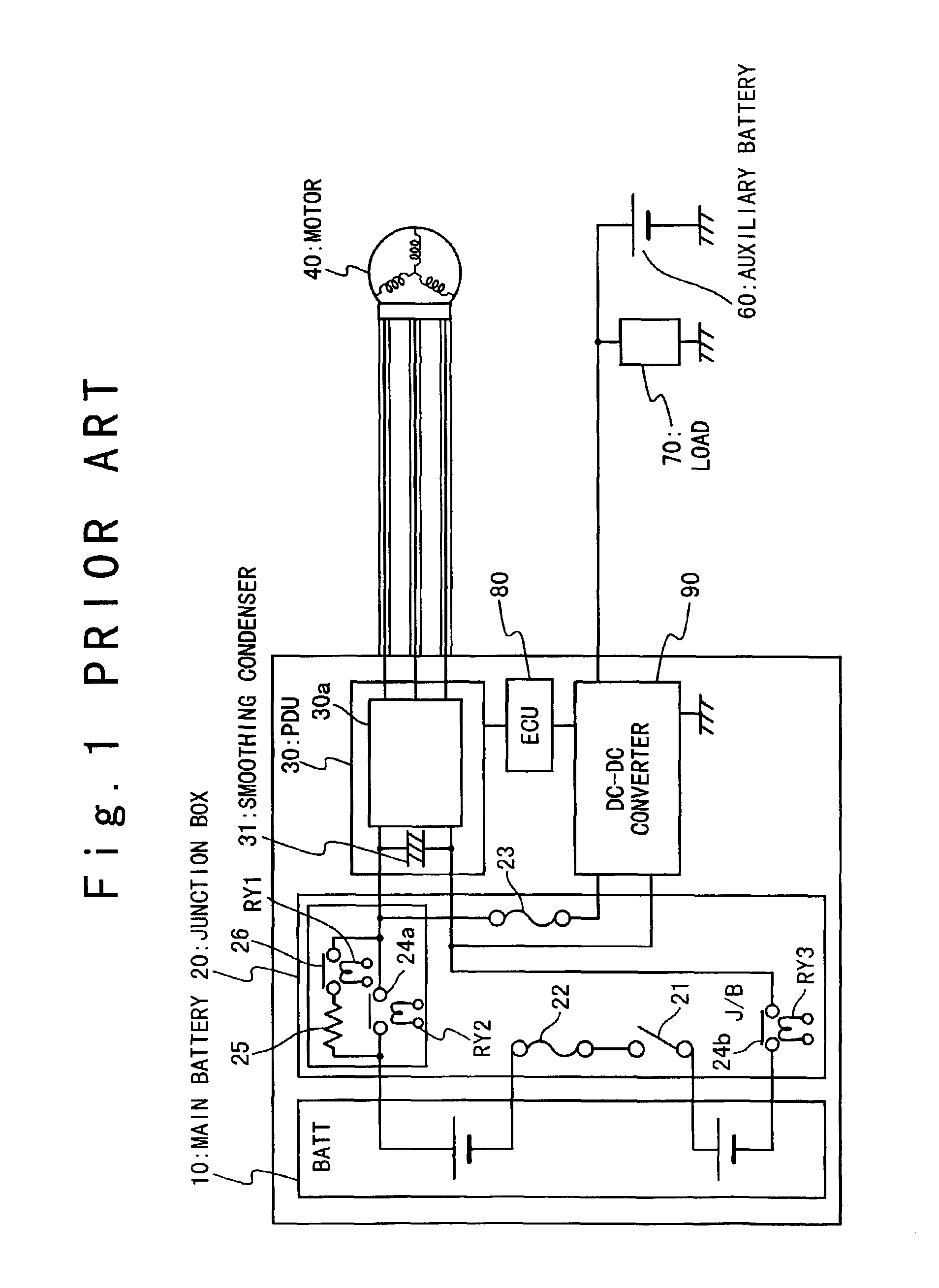
BACKGROUND OF THE INVENTION[0001]1. Field of the Invention[0002]The present invention relates to a power supply apparatus and a vehicle using the same.[0003]2. Description of the Related Art[0004]In recent years, a hybrid electric automobile is developed and has begun to be served to a practical use. FIG. 1 shows an example of a power supply apparatus installed into the hybrid electric automobile. The hybrid electric automobile using the power supply apparatus is comprised of a main battery (BATT) 10, a junction box (J / B) 20, a power drive unit (PDU) 30, a motor 40, an auxiliary battery 60, a load 70, an electronic control unit (ECU) 80 and a DC-DC converter 90.[0005]The main battery 10 stores and outputs the DC power of as high voltage as 144 V. The output of the main battery 10 is supplied to the power drive unit 30 and the DC-DC converter 90 via the junction box 20.[0006]The junction box 20 accommodates a main switch 21, fuses 22 and 23, a main contactor 24a, a sub-contactor 24b,...

Claims


Application Information

Patent Timeline
Patent Type & Authority Patents(United States)
IPC IPC(8): B60L11/18B60L3/00B60K6/04B60K6/00B60K6/20B60K6/28F02D29/06B60K6/485B60K6/54B60L50/16B60W10/26B60W20/00H02J7/00H02M7/48
CPCB60K6/28B60L3/0046B60L11/14B60L2210/14Y02T10/70B60L2270/20Y02T10/7077Y02T10/7241Y02T10/7225B60L2210/40B60L50/16Y02T10/72Y02T10/7072
Inventor SHIMANE, IWAOYANO, MITSUTERUHARA, KAZUHIROASAKAWA, MASANOBUABE, NORIYUKI
Owner HONDA MOTOR CO LTD
Learn More