

Halftone dots, halftone dot forming method and apparatus therefor
- Summary
- Abstract
- Description
- Claims
- Application Information
AI Technical Summary
Benefits of technology
Problems solved by technology
Method used
Image

Examples
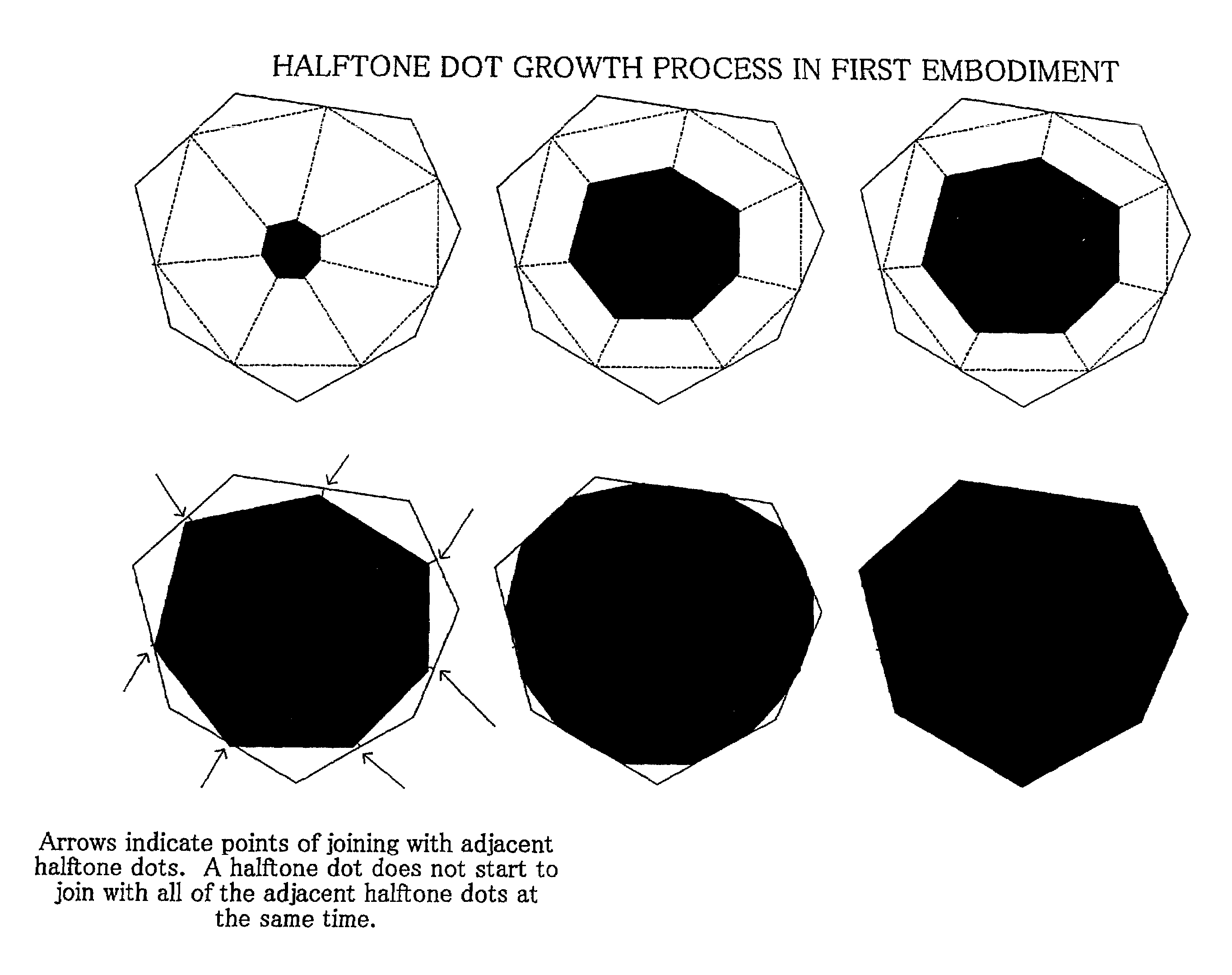
first embodiment
B.
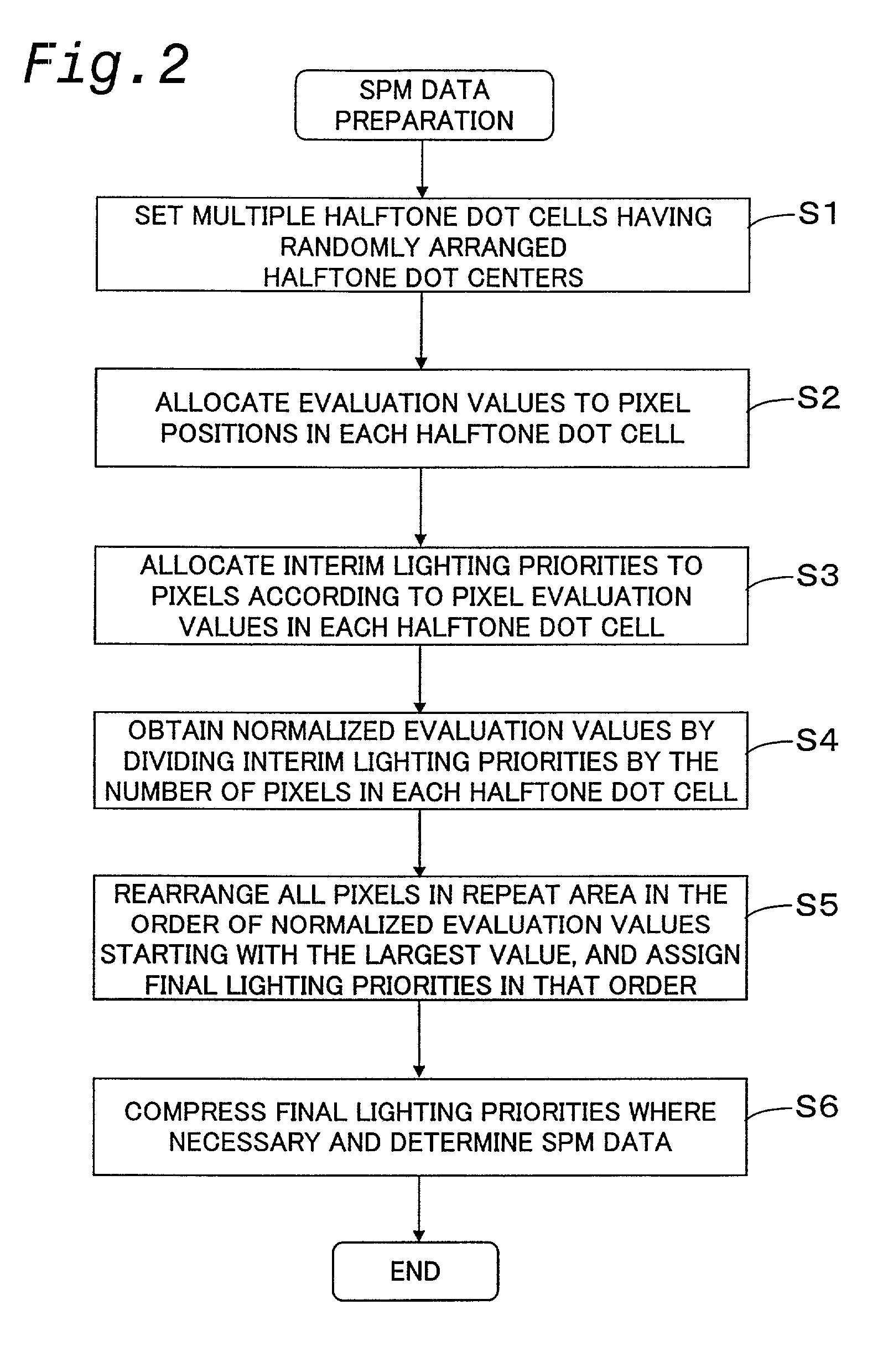
[0040]FIG. 2 is a flow chart showing the process of preparing SPM data for halftone dots in a first embodiment. In step S1, a plurality of halftone dot areas (hereinafter referred to as ‘halftone dot cells’) that have randomly placed halftone dot centers are set. The random arrangement of the halftone dot centers can be attained by a method of solving a facility placement problem using a Voronoi diagram.
[0041]FIG. 3 shows halftone dot centers that are randomly placed. In this example, nine repeat areas RA are arranged in a tiled fashion. A halftone dot center is located at the position of a black dot surrounded by a circle. The nine repeat areas RA in the figure are all identical. A plurality of halftone dot centers and polygons that surround each halftone dot center are drawn in the repeat area RA located in the center in FIG. 3. These polygons are called ‘Voronoi polygons’. A Voronoi polygon is formed by seeking the perpendicular bisectors of the lines that connect a given halft...
second embodiment
C: Second Embodiment
[0071]The halftone dot configuration can be changed in various ways by changing the evaluation value distribution (FIG. 7) that characterizes the halftone dot configuration. FIGS. 11(a) and 11(b) show the setting of the evaluation value distribution in a second embodiment. The halftone dot cell HC is divided into a plurality of triangular areas by connecting the halftone dot center DC and the vertices of the polygon of the halftone dot cell HC with straight lines. As shown in FIG. 11(b), the evaluation value at the halftone dot center DC is then to 1.0, and the evaluation value at each vertex of the halftone dot cell HC is set to (−1.0+α) where α is a positive or negative random number. The calculation method for the evaluation value at each pixel is the same as that explained with reference to FIG. 7(c).
[0072]FIGS. 12(a)–12(f) show the process of the growth of a halftone dot in the second embodiment. In the situation shown in FIG. 12(e), white pixel areas are fo...
modification 1
D1. Modification 1
[0081]In the embodiments described above, the pixels are recorded based on two values of ON and OFF, but the present invention may also be applied when the pixels are recorded based on a plurality of values more than two. FIGS. 15(a) and 15(b) show a comparison of a bi-tone halftone dot and a tri-tone halftone dot. The bi-tone halftone dot consists of pixels recorded based on two value signals, and the tri-tone halftone dot consists of pixels recorded based on three value signals. In the tri-tone halftone dot, the white area includes pixels having a density value of 0, the black area includes pixels having a density value of 1, and the hatched area includes pixels having a density value of 0.5. Such multi-halftone dots can be formed based on essentially the same method as that used in the embodiments described above. For example, the density of each pixel may be determined by assigning n different threshold values to one pixel and comparing the image data and the n...
PUM
 Abstract
Description
Claims
Application Information