Circuit and method for reducing SRAM standby power

a technology of standby power and circuit, applied in the field of electronic circuits, can solve the problems of inability to completely shut down the memory circuit to conserve power, the process of fully powering the memory circuit typically requires much more time, and the manufacturers of portable electronic devices have contrary goals, so as to achieve the effect of greatly reducing the power of standby

Active Publication Date: 2006-01-24
TEXAS INSTR INC
View PDF4 Cites 27 Cited by
  • Summary
  • Abstract
  • Description
  • Claims
  • Application Information

AI Technical Summary

Benefits of technology

[0012]In accordance with a preferred embodiment of the invention, there is disclosed a method of operating a memory circuit. The method includes applying a first voltage to a power terminal of a memory cell having a first and a second data terminal. A data bit is stored in the memory cell. A second voltage different from the first voltage is applied to the power terminal. A third voltage is applied to the first and second data terminals. The first voltage is applied to the power terminal. The memory cell powers up in a state providing minimum leakage. Standby power is greatly reduced.

Problems solved by technology

The continuing popularity of portable electronic devices presents manufacturers with contrary goals.
The process of fully powering these memory circuits typically requires much more time than that required for a memory access in the fully powered state.
However, access times of these memories remains important, so it may not be feasible to completely shut the memory down to conserve power.
Random data states of the memory cells might result in power dissipation similar to all-zero or all-one data states.

Method used


Image

  • Circuit and method for reducing SRAM standby power
  • Circuit and method for reducing SRAM standby power
  • Circuit and method for reducing SRAM standby power

Examples


Embodiment Construction

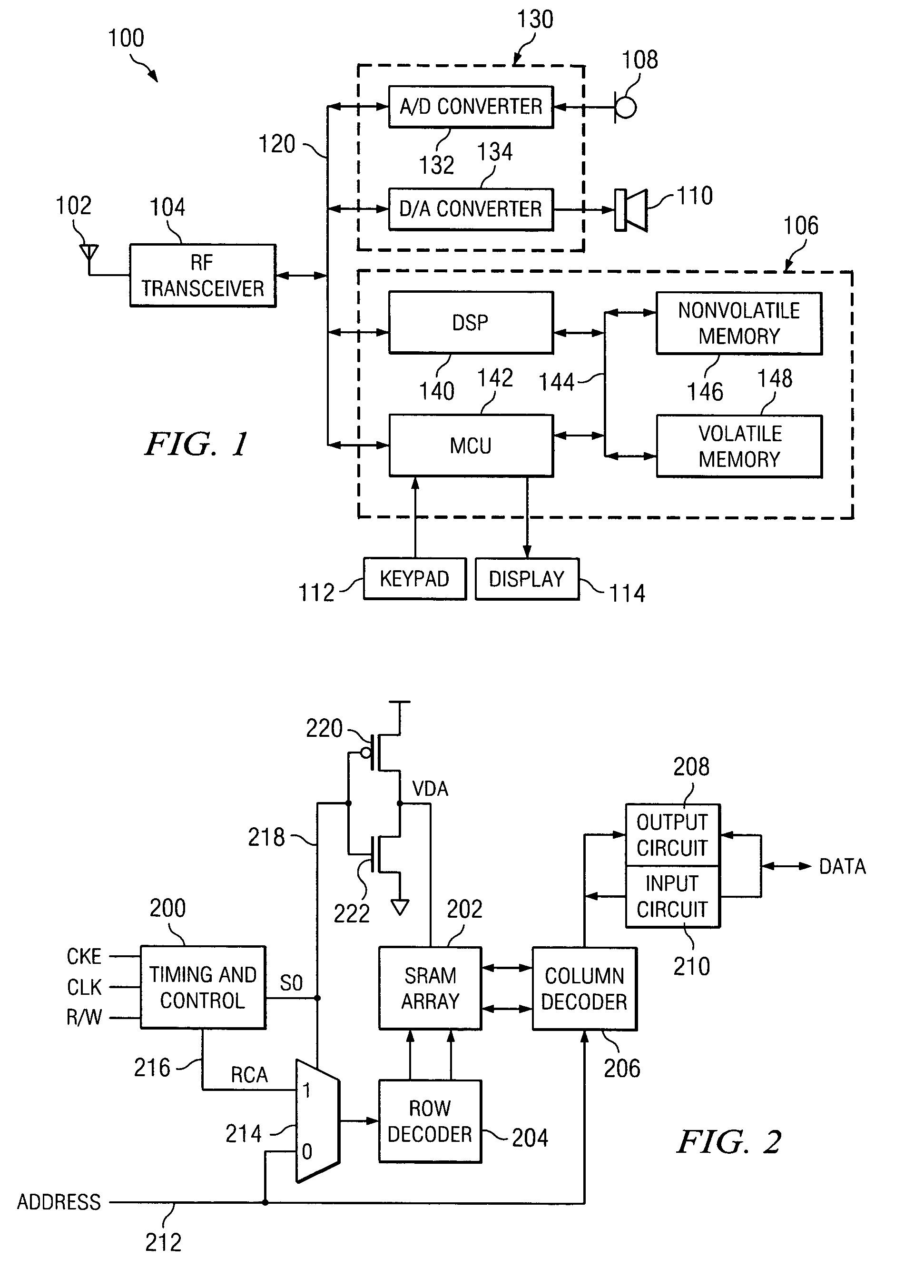
[0021]Referring to FIG. 1, there is a block diagram of a wireless telephone as an example of a portable electronic device which could advantageously employ this invention. Wireless telephone 100 includes antenna 102, radio frequency transceiver 104, baseband circuits 106, microphone 108, speaker 110, keypad 112, and display 114. The wireless telephone is preferably powered by a rechargeable battery (not shown) as is well known in the art. Antenna 102 permits wireless telephone 100 to interact with the radio frequency environment for wireless telephony in a manner known in the art. Radio frequency transceiver 104 both transmits and receives radio frequency signals via antenna 102. The transmitted signals are modulated by the voice / data output signals received from baseband circuits 106 on bus 120. The received signals are demodulated and supplied to baseband circuits 106 as voice / data input signals on bus 120. An analog section 130 includes an analog to digital converter 132 connecte...


PUM


Abstract

A method of operating a memory circuit to reduce standby current is disclosed. The method includes applying a first voltage (Vdd) to a power terminal (224) of a memory cell having a first (612) and a second (614) data terminal. A data bit is stored in a memory cell (600,602,604,606). A second voltage (VDA) different from the first voltage is applied to the power terminal. A third voltage (Ground) is applied to the first and second data terminals. The first voltage is applied to the power terminal.

Description

FIELD OF THE INVENTION[0001]This invention generally relates to electronic circuits, and more specifically to power reduction in semiconductor integrated circuits.BACKGROUND OF THE INVENTION[0002]The continuing popularity of portable electronic devices presents manufacturers with contrary goals. Battery capacity is dependent upon battery size and weight. Thus portable electronic devices could be made to operate a longer time between battery changes or recharging if these devices included heavier batteries with greater capacity. On the other hand, portable electronic devices would be more popular and more widely used if they were lighter. However, lighter weight translates into reduced battery capacity and reduced operating times. A large reduction in size of wireless telephones has taken place without significant reduction in operating times. While improvements in batteries have increased their capacity per unit weight, most of the improvement in operating time and reduction in devi...

Claims


Application Information

Patent Timeline
Patent Type & Authority Patents(United States)
IPC IPC(8): G11C7/00G11C11/417
CPCG11C11/417
Inventor REDWINE, DONALD J.DOERING, ROBERT R.
Owner TEXAS INSTR INC
Why Eureka
Try Eureka