Photogrammetric measurement system and method

Active Publication Date: 2006-01-24
GEODETIC SERVICES
View PDF4 Cites 69 Cited by
  • Summary
  • Abstract
  • Description
  • Claims
  • Application Information

AI Technical Summary

Benefits of technology

[0023]The features that characterize the invention, both as to organization and method of operation, together with further objects and advantages thereof, will be better understood from the following description used in conjunction with the accompanying drawing. It is to be expressly understood that the drawing is fo

Problems solved by technology

In-line production measurements are also impossible using CMM systems.
For many applications, access to the object is limited, making setup of the instrument difficult.
Furthermore, touching the desired features with the measuring device can be difficult, tedious, and prone to lead to measurement errors.
One limiting factor in the use of photogrammetry for feature measurement in the past has been the need for point-of-interest targeting.
The time penalty for these adapters comes at the processing stage, when they need to be ide

Method used


Image

  • Photogrammetric measurement system and method
  • Photogrammetric measurement system and method
  • Photogrammetric measurement system and method

Examples


first embodiment

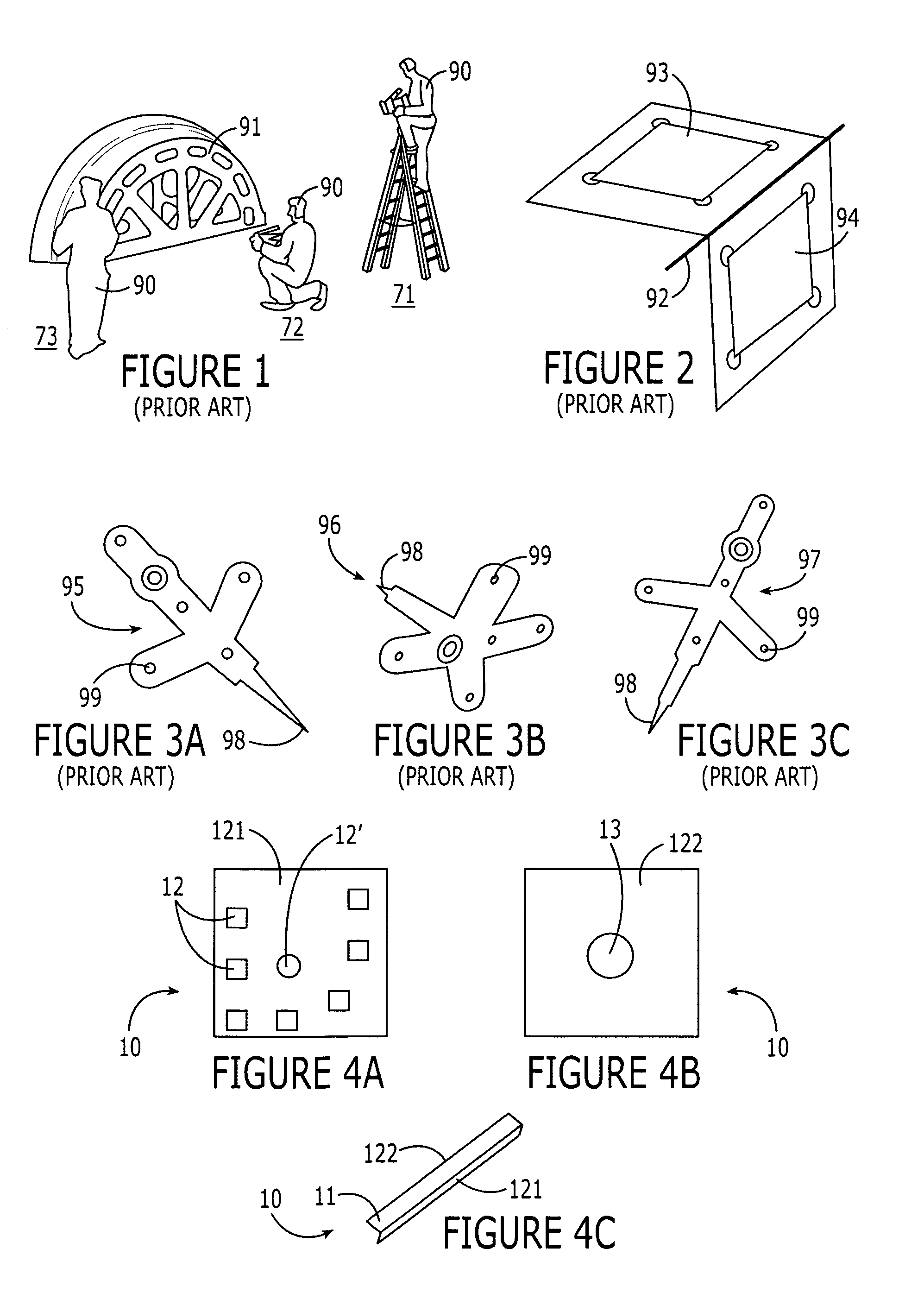
[0044]the FT 10 is for measuring a plane. This FT (FIGS. 4A–4C) comprises a planar base 11, comprising, for example, a flat piece of aluminum. The top side 121 of the base 11 has a plurality of coded targets 12,12′ thereon (FIG. 4A); the bottom side 122 of the base 11 has at least one magnet 13 embedded therein to hold the FT 10 in place. This positioning device is exemplary and is not intended to be limiting, and it will be understood by one of skill in the art that alternate affixing methods are able to be substituted therefor, such as an adhesive for affixing to nonmetallic portions of objects. The relationship between the targets 12,12′ on the top side 121 of the base 11 and the plane represented by the base 11 is determined by a one-time calibration.

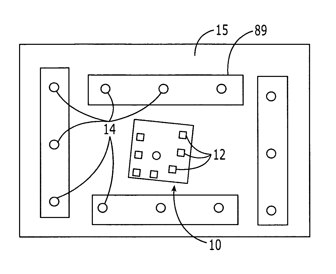
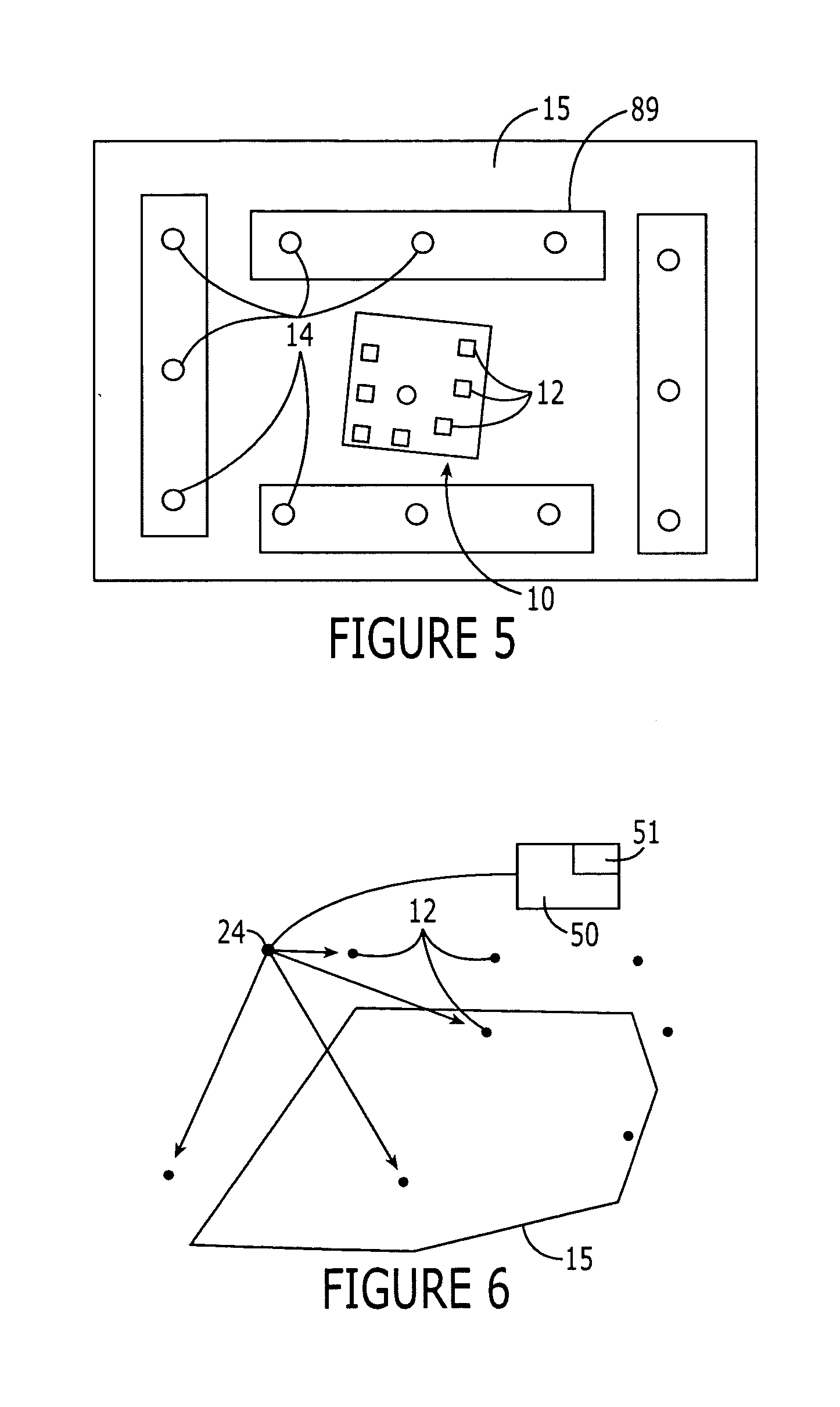
[0045]The FT 10 is placed on a flat surface 89 such as granite (FIG. 5). Retroreflective targets 14 are placed adjacent the FT 10 and are used to define a “local” plane 15. A photogrammetric measurement is then made to determine the...

case 1 (fig.9a)

[0060]In Case 1 (FIG. 9A), analysis of production tooling requires a fast and efficient measurement system. The driving factors are time and availability for analysis. Case 2 (FIG. 9B) illustrates the need for immediate information for decision making during production. In both cases the need for uninterrupted production schedules is deemed extremely important.

[0061]In the case of production tooling measurement, unavailability of tooling during after-shift hours due to routine maintenance needs, and constantly changing production schedules due to high product demand, has forced inspection personnel into working during scheduled break times. This means finding a way to measure a tool during a normal 40-min lunch break with the goal of eventually completing the measurement during a 10-min coffee break.

[0062]The ability to flexibly analyze product deviation in-line is the focus of the second case study. Increasingly, inspection is needed at the point of origin in order to efficiently d...

case 1

[0063] In this study a 1.8-m-long panel-holding fixture (FIG. 9A) is desired to be measured, to determine the location of features such as corners, edges, and planes on the fixture.

[0064]An FT 10 was placed on each of the desired features. Where possible, one was used. For features without a suitable target, the necessary data were created using a combination of FTs.

[0065]An exemplary sample clamping mechanism is illustrated in FIG. 10, wherein four FTs 20–23 are shown. The FT 20 at the back of the clamp 88 is used to define a contact plane. The three remaining FTs 21–23 define the hard corner of the clamping surface. The fixture measurement required a total of 40 FTs to measure all the desired features.

[0066]After targeting a total of 60 photographs were taken of the fixture 88. The number of photographs taken depends on the complexity of the measurement and accuracy requirements. The photography for the fixture 89 was completed in approximately 5 min. Camera station locations 24 f...


PUM


Abstract

A method for characterizing a geometric element of an object includes positioning a calibrated target adjacent a calibration geometric element, the calibrated target having at least two differentially detectable features having a known geometric relationship to each other. Next a relationship of the calibrated target to the calibration geometric element is determined, and the calibrated target is moved adjacent a geometric feature of an object desired to be characterized. Then photogrammetry is applied to the calibrated target features and the desired geometric feature to spatially characterize the desired geometric feature. A system for characterizing a geometric element of an object includes the movable calibrated target and a photogrammetric analysis system for determining a relationship of the calibrated target to a calibration geometric element and for spatially characterizing the desired geometric feature using the calibrated target features.

Description

CROSS-REFERENCE TO RELATED APPLICATION[0001]This application claims priority from provisional application No. 60 / 221,702, filed Jul. 31, 2000, entitled “Photogrammetric Measurement System and Method.”BACKGROUND OF THE INVENTION[0002]1. Field of the Invention[0003]The present invention relates to systems and methods for remote measurement of geometric features on an object, and, more particularly, to such systems and methods that are photogrammetrically based.[0004]2. Description of Related Art[0005]Photogrammetry is a fast, accurate three-dimensional measurement method based on photographic principles. In a single-camera or sequential mode of photogrammetry, a single high-resolution digital camera takes multiple pictures of an object from different locations. These pictures are then automatically processed to yield three-dimensional coordinates of points on an object (Ganci and Handley, 1998).[0006]The sequential mode is not real time; so it can only measure static objects and targe...

Claims


Application Information

Patent Timeline
IPC IPC(8): G06K9/00
CPCG01C11/02
Inventor BROWN, JOHN D.GANCI, GIUSEPPEHANDLEY, HARRY B.
Owner GEODETIC SERVICES
Why Eureka
Try Eureka