
Apparatuses and methods for surgical navigation

a surgical and apparatus technology, applied in the field of apparatus and methods for surgical navigation, can solve the problems of obstructing the surgeon physically, a plurality of fluoroscopic images, and unable to compute the derivatives and uses by automatic means,

Inactive Publication Date: 2006-01-24
IGO TECH
View PDF24 Cites 212 Cited by
  • Summary
  • Abstract
  • Description
  • Claims
  • Application Information

AI Technical Summary

Benefits of technology

"The invention provides a method of surgical navigation that allows for the accurate positioning of a patient and the creation of a virtual surface of creation for surgery. The method involves acquiring images of the patient and the surface of creation, setting a virtual surface of creation with respect to the patient, and projecting a virtual image of a tool or a virtual guard onto the virtual surface of creation to guide the surgery. The method can be used with a projective imaging system and can be adapted for different surgical procedures."

Problems solved by technology

A deficiency in existing use of two-dimensional images is that the derivation of three-dimensional geometry, and useful inferences therefrom, rely principally on the skill of the observer and the derivations and uses are not easily computed by automatic means.
At least two problems arise from taking a plurality of fluoroscopic images during the course of operating on a patient.
The fluoroscope can physically obstruct the surgeon who is performing the operation.
At least one deficiency of the above method is that three-dimensional guidance from multiple two-dimensional images is inherently difficult because multiple two-dimensional images may be misinterpreted.
The practitioner would require considerable prior understanding of normal and pathological anatomy, and might be inconvenienced by the physical presence of the fluoroscope during the drilling process.
For said examples of a skilled practitioner using only fluoroscopic images and of a skilled practitioner using computer-generated images, it is possible that the practitioner might pierce the femoral head and thereby cause vile undesired consequences to the health of the patient.
Similar problems occur with tomographic images because two-dimensional projection images and two-dimensional tomographic images are not adequate representations of three-dimensional geometry.

Method used


Image

  • Apparatuses and methods for surgical navigation
  • Apparatuses and methods for surgical navigation
  • Apparatuses and methods for surgical navigation

Examples


Embodiment Construction

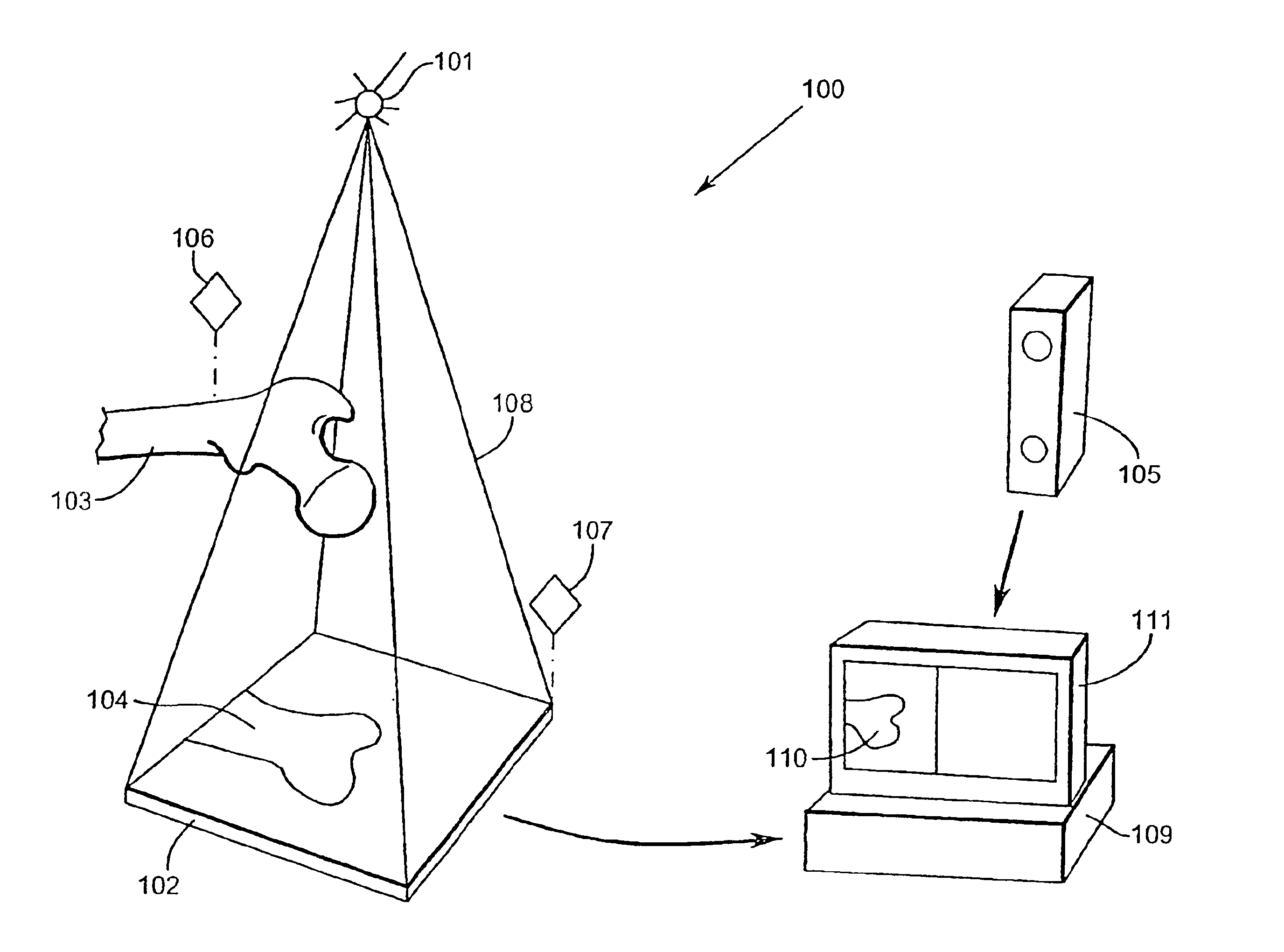
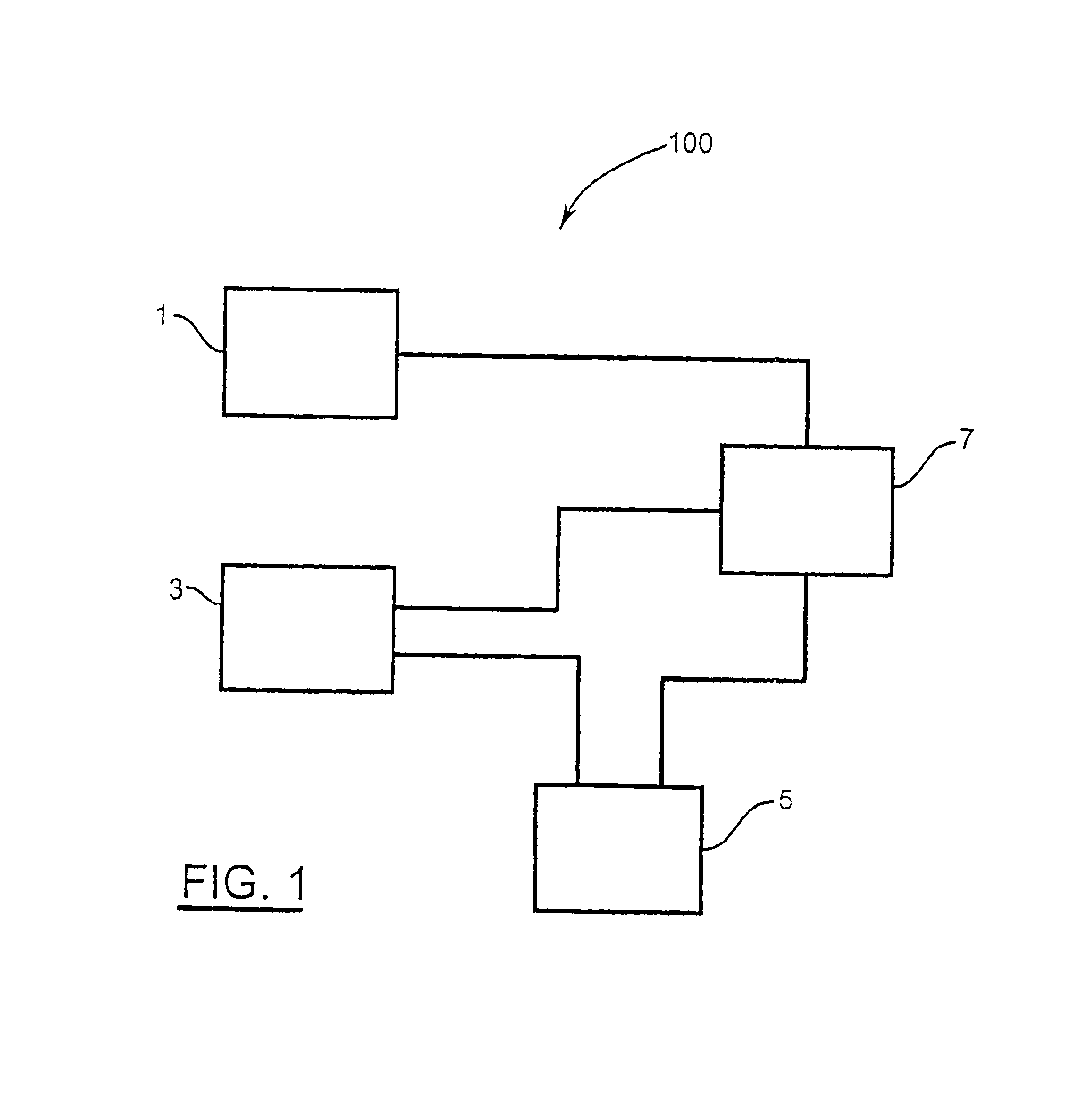
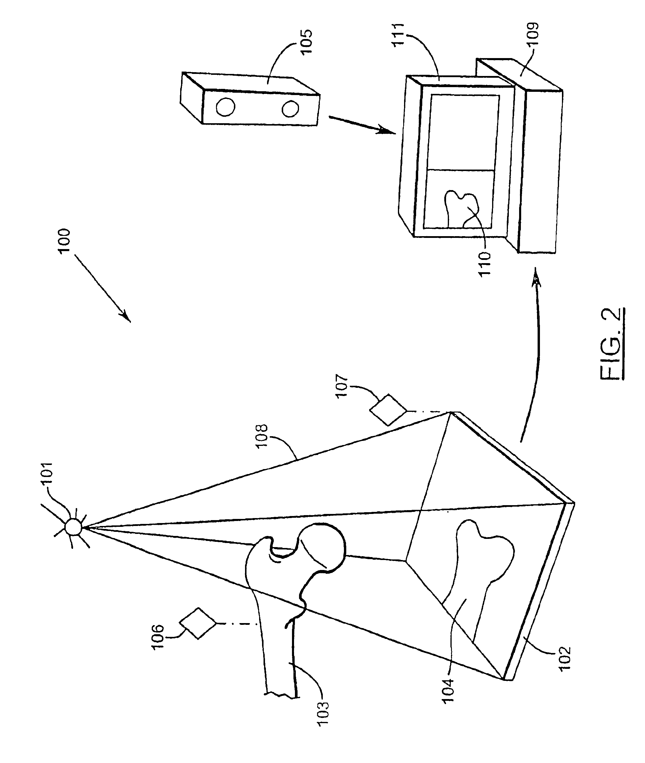
[0056]Referring to FIG. 1, an imaging apparatus 100 is used for representing and manipulating three-dimensional geometry derived from multiple two-dimensional images.

[0057]For brevity, this paragraph defines certain terms that will be used in this description. The position and orientation of a geometrical entity or physical object will be called the “pose” of the entity or object, where it is understood that the orientation of a point is arbitrary and that the orientation of a line or a plane or other special geometrical objects may be specified with only two, rather than the usual three, orientation parameters. A geometrical entity with known three-dimensional geometry will hereafter be called a “guard”. A three-dimensional computer representation of the shape, surface, or volume of a geometrical entity will hereafter be called a “form”. A coordinate frame, relative to a physical object that is imaged by the imaging device, will hereafter be called an “anatomical coordinate frame”....


PUM


Abstract

Imaging, object tracking, integration apparatus 100 has tracking system 1, imaging system 3, communication system 5 and integration system 7. Tracking system 1 locates objects in 3-dimensions and determines respective poses. Imaging system 3 acquires object images. Integration system 7 correlates 3-dimensional poses. User communication system 5 provides information, such as images, sounds, or control signals to the user or other automated systems. Image acquisition techniques include X-ray imaging and ultrasound imaging. Images can be acquired from digital files. Imaging system 3 creates a calibrated, geometrically corrected two-dimensional image 110, 210. Correlation system 7 can receive instructions from a practitioner to create, destroy, and edit the properties of a guard. Communications system 5 displays images and calculations to a practitioner, such as a surgeon. Methods can determine geometrical relations between guards and / or present to a practitioner projections of forms of guards.

Description

FIELD OF THE INVENTION[0001]The invention is related to the inference, representation, and manipulation of three-dimensional geometry derived from two or more two-dimensional images.BACKGROUND OF THE INVENTION[0002]Many current medical, manufacturing and inspection practices rely on relating three-dimensional geometry to two-dimensional projection or tomographic images. An example of a projection image is a plain radiograph, in which electromagnetic energy transmitted and refracted through or by physical objects, until film or another process, such as a digital process, creates an image. Examples of tomographic imaging technologies include, but are not limited to, computed tomography, magnetic resonance imaging, ultrasound imaging, positron emission tomography, and single photon emission computed tomography. An example of a tomographic image is an ultrasound image, in which acoustic energy transmitted and refracted through or by physical objects, until a process, such as a digital p...

Claims


Application Information

Patent Timeline
Patent Type & Authority Patents(United States)
IPC IPC(8): G06K9/00G16H30/40
CPCG06F19/3437A61B2019/5265Y10S128/922G06F19/321A61B2034/2065G16H50/50G16H30/40
Inventor ELLIS, RANDY E.RADCLIFFE, THOMAS J.
Owner IGO TECH
Learn More