Multi-bandwidth collimator

Inactive Publication Date: 2006-01-24
CORNING INC
View PDF8 Cites 22 Cited by
  • Summary
  • Abstract
  • Description
  • Claims
  • Application Information

AI Technical Summary

Benefits of technology

[0006]The invention relates to a collimator for use at multiple wavelengths. In one embodiment, the collimator comprises an optical fiber and a gradient index lens positioned at a constant distance with respect to an end of the optical fiber. In one aspect, the gradient index le

Problems solved by technology

If the fiber-to-lens distance is not adjusted to compensate for this offset, the collimator could have excessive insertion loss, particularly if there is a great disparity between the design wavelength and the operating wavelength.
As can be appreciated, the need to readjust the fiber-to-lens distance for each operating wavelength complicates use of the collimator in multi-bandwidth applications.

Method used


Image

  • Multi-bandwidth collimator
  • Multi-bandwidth collimator
  • Multi-bandwidth collimator

Examples


Embodiment Construction

[0016]The invention will now be described in detail with reference to a few preferred embodiments, as illustrated in accompanying drawings. In the following description, numerous specific details are set forth in order to provide a thorough understanding of the invention. However, it will be apparent to one skilled in the art that the invention may be practiced without some or all of these specific details. In other instances, well-known features and / or process steps have not been described in detail in order to not unnecessarily obscure the invention. The features and advantages of the invention may be better understood with reference to the drawings and discussions that follow.

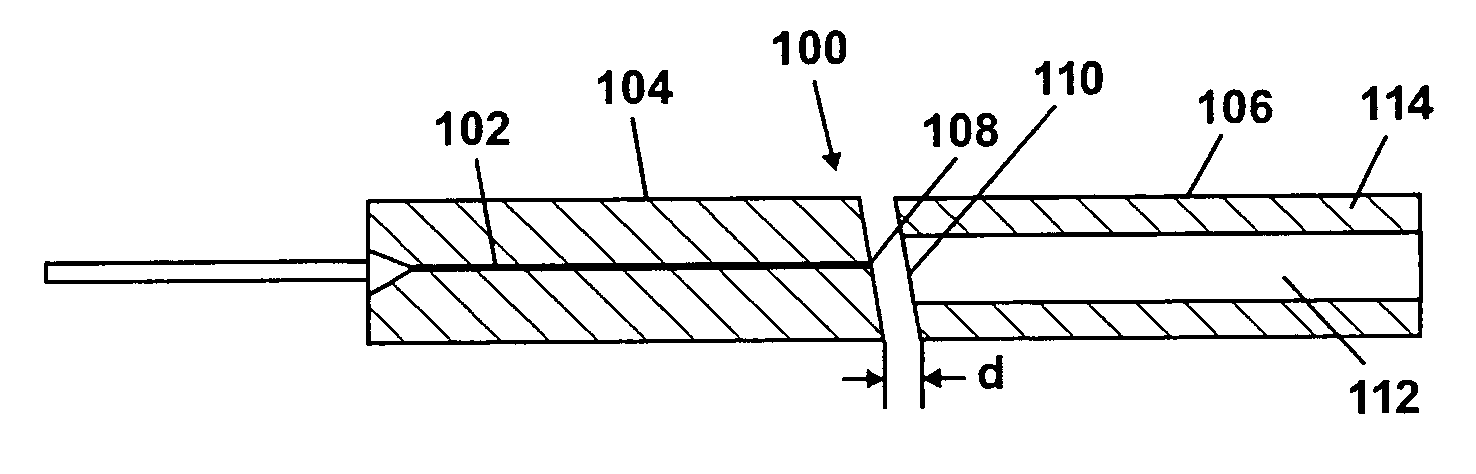
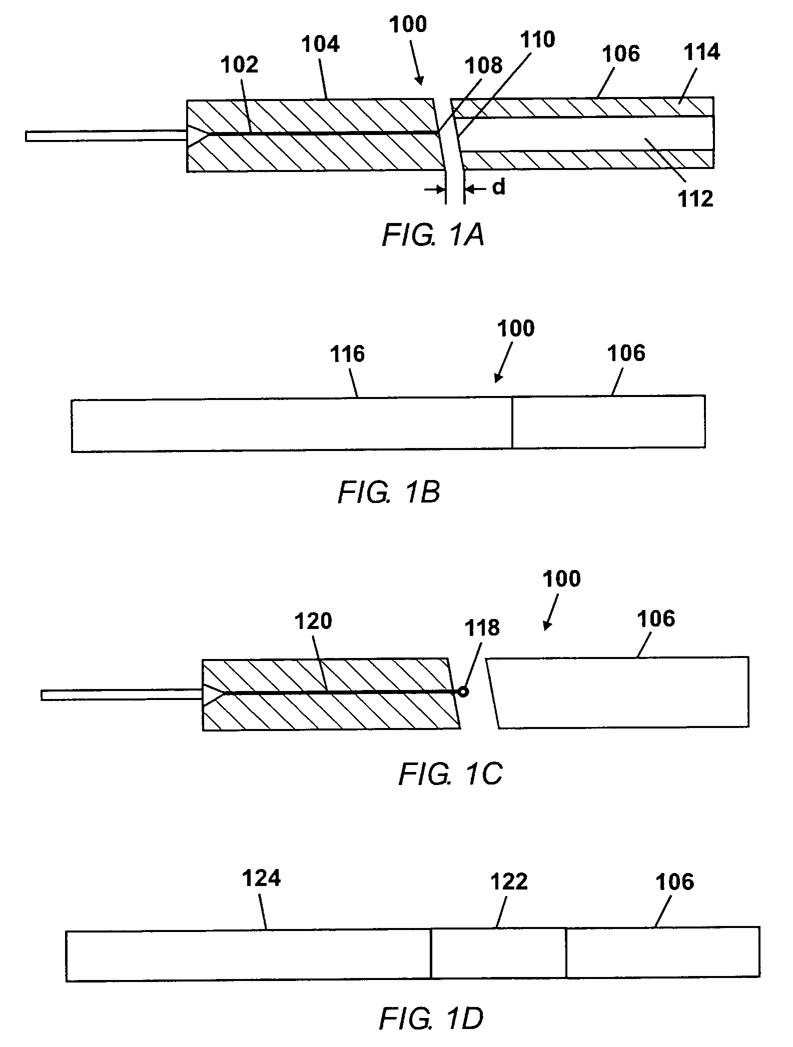
[0017]Embodiments of the invention provide a collimator having a GRIN lens positioned at an end of an optical fiber. The collimator can be tuned at a particular design wavelength and then operated efficiently over a wide range of wavelengths including the design wavelength without having to readjust the dist...


PUM


Abstract

A collimator for use at multiple wavelengths includes an optical fiber and a gradient index lens positioned at a constant distance with respect to an end of the optical fiber. The gradient index lens has a chromatic aberration at a selected pitch less than 0.01 over a selected range of the infrared spectral region.

Description

CROSS REFERENCES TO RELATED APPLICATIONS[0001]This application claims the benefit of U.S. Provisional Application Ser. No. 60 / 465,830, filed Apr. 25, 2003.BACKGROUND OF THE INVENTION[0002]The assembly of a fiber end with a lens for producing a substantially parallel beam from light emerging from the fiber end is called a “collimator.” The lens could be a gradient index (GRIN), refractive, or diffractive lens. Herein, the focus is on a collimator incorporating a GRIN lens. The GRIN lens has an index of refraction that gradually varies from the axis of the lens towards the outer periphery of the lens. In a GRIN lens, rays of light follow sinusoidal paths whose trajectory is defined in terms of pitch. One pitch is equivalent to the light traversing one sinusoidal cycle and can be expressed as follows: P=L⁢A2⁢⁢π(1)where P is pitch, √{square root over (A)} is index gradient parameter, and L is length of the lens.[0003]The collimator is assembled by placing the fiber end a distance from t...

Claims


Application Information

Patent Timeline
IPC IPC(8): G02B6/32G02B27/30G02B7/02G02B3/00G02B6/26
CPCG02B3/0087G02B6/32G02B6/262
Inventor GAFSI, RACHIDMANN, LARRY GSHASHIDHAR, NAGARAJA
Owner CORNING INC
Why Eureka
Try Eureka