Yarn false twist texturing machine

a texturing machine and yarn technology, applied in the field of yarn false twist texturing machine, can solve the problems of more processing units and inability to control individual processing stations, and achieve the effect of increasing the flexibility of the texturing machin

Inactive Publication Date: 2006-01-31
SAURER GMBH & CO KG
View PDF14 Cites 2 Cited by
  • Summary
  • Abstract
  • Description
  • Claims
  • Application Information

AI Technical Summary

Benefits of technology

[0007]The invention thus has the advantage that a group frequency changer may be provided which permits activating the individual drives in a simple manner so that only a desired frequency is applied to each individual drive. In this connection, the desired frequency forms the operating state (e.g. rotational speed) that is necessary for the processing unit. In the individual drive, the asynchronous unit sees to it that after starting up, the individual drive starts operating directly until the desired frequency is reached. Upon reaching the desired frequency, the synchronous unit of the individual drive becomes operative and prevents the processing unit from being driven with a frequency that deviates from the desired frequency. The processing unit thus reaches automatically an operating state that corresponds to the desired frequency. With that, it is possible to use a group frequency changer for controlling a plurality of individual drives in a simple manner. After each connection, it is thus possible to operate the processing units of a functional group in the operating state reliably with the respectively predetermined desired parameters. This ensures an identical treatment of all yarns in the processing stations.
[0009]It is preferred to form the synchronous unit by a synchronous motor, which comprises as an asynchronous unit an auxiliary winding arranged on the rotor. This ensures that during an activation of the individual drive at a constantly predetermined desired frequency, the synchronous motor starts up without delay, until the rotor of the synchronous motor is in sync with the rotating field of the stator.
[0010]To enable an individual startup and shutdown of the processing stations independently of one another, a very advantageous further development of the invention proposes to connect each of the individual drives of the group of processing units to the group frequency changer via a controllable switching element. This makes it possible to shut down one or more of the individual drives associated to the group frequency changer without influencing adjacent individual drives and processing units.
[0011]Moreover, it will be of advantage, when each of the individual drives comprises a sensor for monitoring the rotational speed. This sensor connects to a control unit that controls the switching elements. Thus, it is possible to avoid with advantage an overload of the individual drives by a comparison of actual and desired values.
[0013]With the use of a plurality of individual drives for a plurality of processing units, one frequency changer each is associated to the individual drives of a group of processing units, with all group frequency changers being coupled with the machine control system. To increase the flexibility of a texturing machine, a further advantageous embodiment of the invention proposes to divide the plurality of processing stations into one or more sections, with each section comprising a plurality of processing stations. In this case, the group frequency changers of the section connect to a field control system that is connected to the section. The processing units of the processing stations in the particular section can thus be controlled independently of the processing units of the processing stations of adjacent sections.
[0014]The processing units driven by individual drives may advantageously be formed for each processing station by a first feed system, and / or a second feed system, and / or a third feed system. This makes it possible to adjust and vary in an accurate manner both the yarn speed and the draw ratio for drawing the yarn.

Problems solved by technology

However, this variant has in general the disadvantage that it does not permit an individual control of the processing stations.
However, it has now been found that the individual activation of the processing stations results in that the individual drives of the processing units are more often connected and disconnected separately from one another.

Method used


Image

  • Yarn false twist texturing machine
  • Yarn false twist texturing machine
  • Yarn false twist texturing machine

Examples


Embodiment Construction

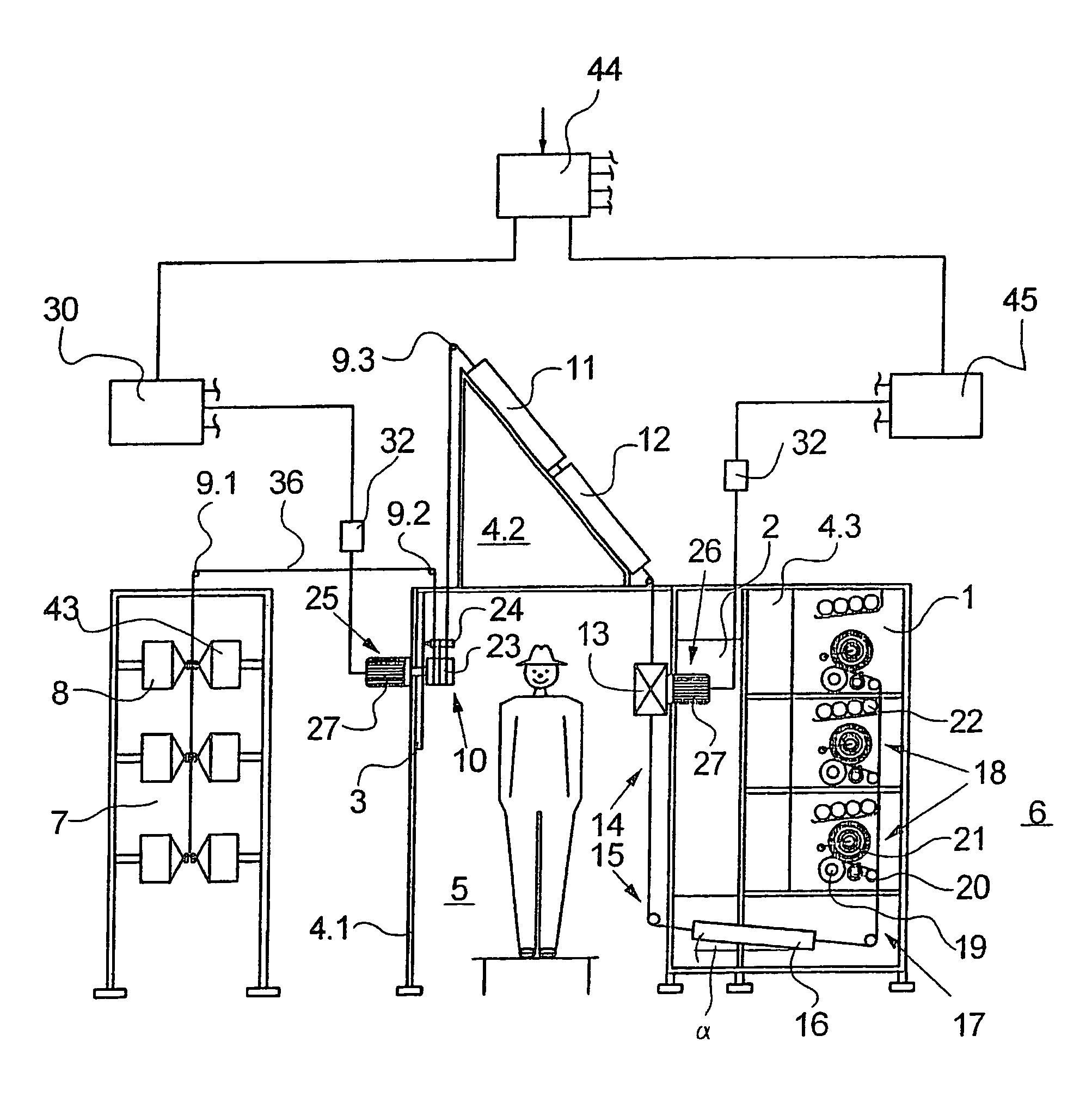
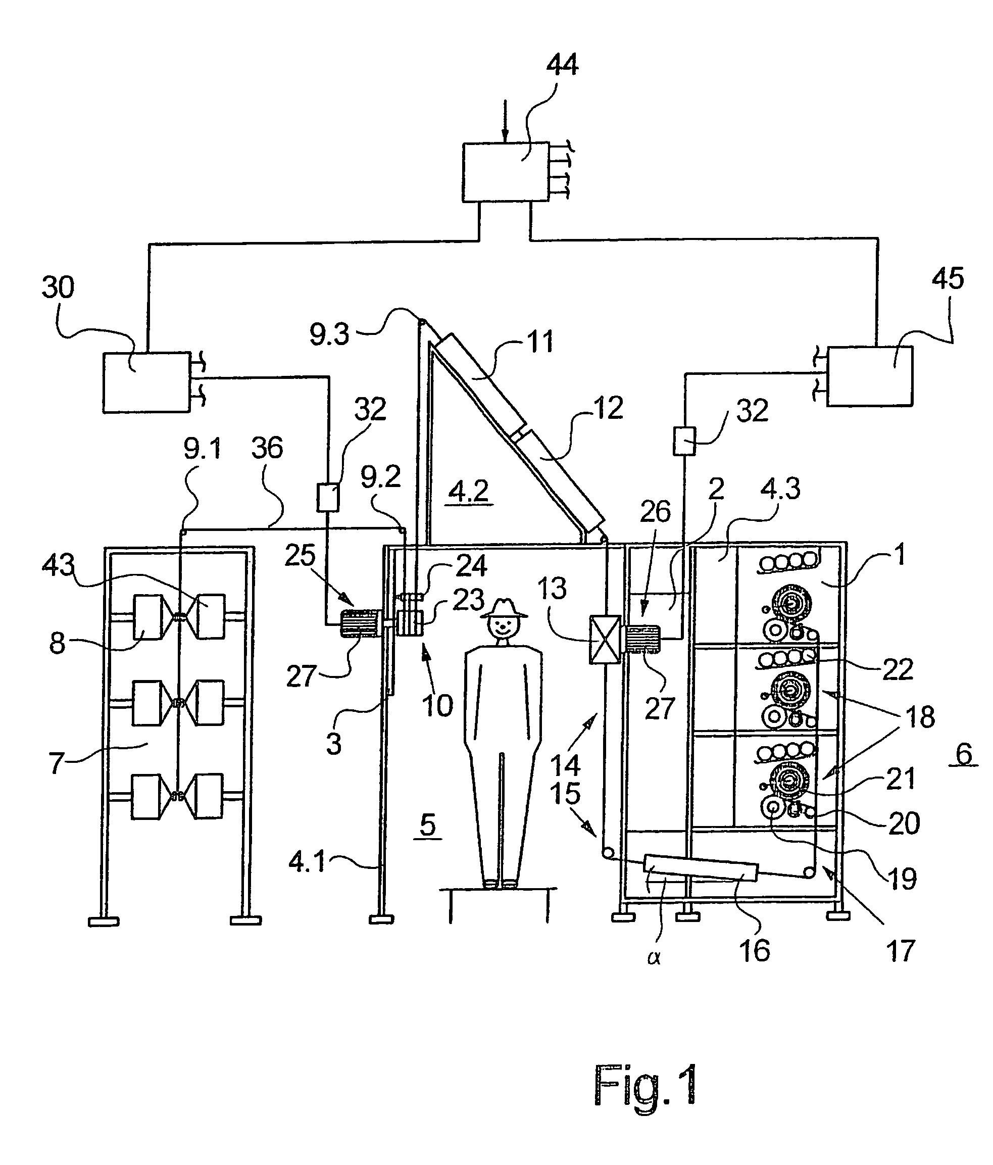
[0023]FIG. 1 schematically illustrates a first embodiment of a yarn texturing machine according to the invention. The texturing machine comprises a feed module 3, a processing module 2, and a takeup module 1, which are arranged in a machine frame composed of frame sections 4.1, 4.2, and 4.3. The frame section 4.1 mounts the feed module 3, and the frame section 4.3 mounts the processing module 2 and takeup module 1. The frame sections 4.1 and 4.3 are interconnected by frame section 4.2, which is arranged above the feed module 3 and processing module 2. Between the processing module 2 and the feed module 3, a service aisle 5 extends below the frame section 4.2. In the frame section 4.2, the processing module 2 is arranged on the side facing the service aisle 5, and the takeup module 1 on the opposite side thereto.

[0024]A doffing aisle 6 is provided along the takeup module 1. In its longitudinal direction (in FIG. 1, the plane of the drawing corresponds to the transverse plane) the tex...


PUM

PropertyMeasurementUnit
temperatureaaaaaaaaaa
angleaaaaaaaaaa
frequencyaaaaaaaaaa

Abstract

A texturing machine for draw texturing a plurality of synthetic multi-filament yarns and which includes a plurality of side by side processing stations. Each of the processing stations comprises a plurality of processing units for advancing, texturing, drawing, and winding the yarn. At least one of the processing units is driven by an electrical individual drive, with the individual drives of the processing units of adjacent processing stations being controlled by a common group frequency changer. To enable a separate connection and disconnection of the individual drives with a simultaneous group control, the electrical individual drive of each processing unit includes an asynchronous unit and a synchronous unit. In the case of a predetermined desired frequency, this permits an automatic startup and maintenance of the desired frequency, which leads to a high degree of uniformity of the yarn treatment in each processing station.

Description

CROSS REFERENCE TO RELATED APPLICATION[0001]The present application is a continuation of international application PCT / EP03 / 01486 filed 14 Feb. 2003 and designating the U.S. The disclosure of the referenced international application is incorporated herein by reference.BACKGROUND OF THE INVENTION[0002]The invention relates to a texturing machine for draw texturing a plurality of synthetic multi-filament yarns. A texturing machine of this general type is disclosed in DE 100 26 942 A1 and Patent Publication US 2002 / 0088218A1.[0003]For draw texturing a plurality of yarns, texturing machines of the described type possess a corresponding plurality of side by side processing stations. Each of the processing stations comprises a plurality of processing units, such as, for example, feed systems, false twist texturing units, and takeup devices, which serially advance, texture, draw, and wind the yarn to a package.[0004]To drive the processing units, basically two different variants are known....

Claims


Application Information

Patent Timeline
Patent Type & Authority Patents(United States)
IPC IPC(8): D01H13/32D02G1/02
CPCD02G1/0266D02G1/02G01N33/36
Inventor WORTMANN, THOMASSPRINGMEIER, FRANKLIEBER, REINHARD
Owner SAURER GMBH & CO KG
Why Eureka
Try Eureka