
Microfluidic analytical system with position electrodes

a microfluidic and position electrode technology, applied in the field of analytical devices, can solve problems such as difficult to transport small volumes of liquid, difficult control,

Active Publication Date: 2006-01-31
LIFESCAN IP HLDG LLC +2
View PDF17 Cites 149 Cited by
  • Summary
  • Abstract
  • Description
  • Claims
  • Application Information

AI Technical Summary

Benefits of technology

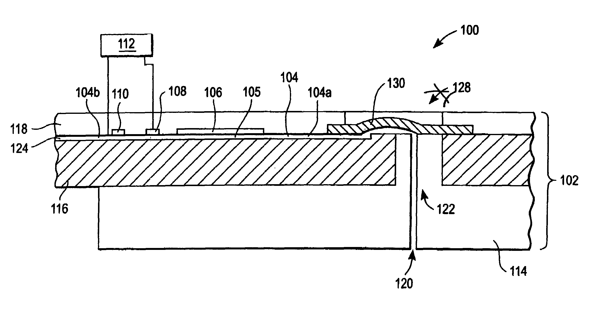
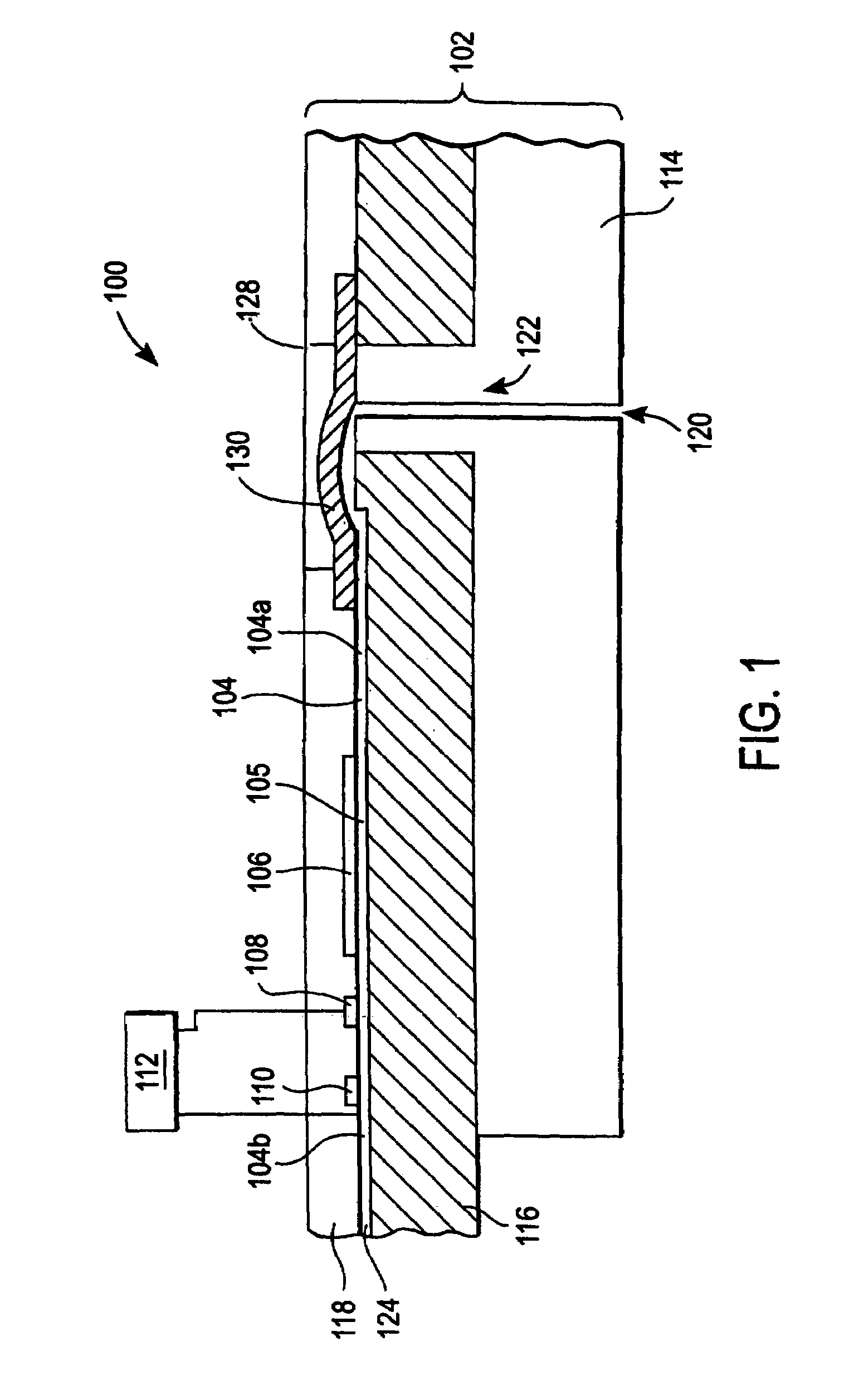
The present invention provides microfluidic analytical systems that can control small volumes of liquid samples and alleviate problems associated with conventional methods. These systems include a micro-channel for receiving and transporting liquid samples, an analyte sensor for measuring an analyte in the liquid sample, and a position electrode in operative communication with the analyte sensor. The system also includes a meter for measuring an electrical characteristic (e.g., impedance or resistance) of the position electrode. The measured electrical characteristic is dependent on the position of the liquid sample in the micro-channel, which enables accurate detection of liquid sample position, flow rate determination, and volume determination.

Problems solved by technology

The relatively small size of the liquid samples and micro-channels in microfluidic analytical devices can, however, render such control problematic.
A challenge of continuous or semi-continuous glucose monitoring systems is that only small volumes of liquid sample (e.g., an ISF liquid sample of about 250 nanoliters) are generally available for measuring a glucose concentration.
In addition, it is difficult to transport small volumes of liquid from a target site to an ex vivo glucose monitor with a controlled flow rate and in such a way that the position and total volume of extracted fluid is known.

Method used


Image

  • Microfluidic analytical system with position electrodes
  • Microfluidic analytical system with position electrodes
  • Microfluidic analytical system with position electrodes

Examples


example

[0097]An interdigitated configuration similar to that of FIG. 13 was tested by employing a phosphate buffer solution as a liquid sample. The first and second position electrodes of the configuration were formed from Ag / AgCl using a screen printing technique. In addition, the first position electrode and second position electrode were separated by a distance Wg of 4 millimeters.

[0098]A potential waveform was applied between the first and second position electrodes with a frequency of 0.25 MHz, an amplitude of + / −0.1 volts, and a RMS of 0 volt. Based on the resulting current between the first and second position electrodes, measured total resistance RT and total measured admittance were calculated (it should be noted that AT=1 / RT). FIG. 21 shows that the measured total admittance AT increases linearly as successive liquid sample boluses pass each of the electrode fingers of the configuration.

[0099]FIG. 21 illustrates that each successive bolus was detected as a change in admittance. T...


PUM

PropertyMeasurementUnit
volumeaaaaaaaaaa
frequencyaaaaaaaaaa
widthaaaaaaaaaa

Abstract

A microfluidic analytical system for monitoring an analyte (for example, glucose) in a liquid sample (e.g., ISF) includes an analysis module with at least one micro-channel for receiving and transporting a liquid sample, at least one analyte sensor for measuring an analyte in the liquid sample and at least one position electrode. The analyte sensor(s) and position electrode(s) are in operative communication with the micro-channel. The microfluidic system also includes a meter configured for measuring an electrical characteristic (such as impedance or resistance) of the position electrode(s). Moreover, the measured electrical characteristic is dependent on the position of the liquid sample in the micro-channel that is in operative communication with the position electrode for which an electrical characteristic is measured.

Description

BACKGROUND OF INVENTION[0001]1. Field of the Invention[0002]The present invention relates, in general, to analytical devices and, in particular, to microfluidic analytical systems.[0003]2. Description of the Related Art[0004]In analytical devices based on liquid samples (i.e., fluidic analytical devices), the requisite liquid samples should be controlled with a high degree of accuracy and precision in order to obtain reliable analytical results. Such control is especially warranted with respect to “microfluidic” analytical devices that employ liquid samples of small volume, for example, 10 nanoliters to 10 microliters. In such microfluidic analytical devices, the liquid samples are typically contained and transported in micro-channels with dimensions on the order of, for example, 10 micrometers to 500 micrometers.[0005]The control (e.g., transportation, position detection, flow rate determination and / or volume determination) of small volume liquid samples within micro-channels can b...

Claims


Application Information

Patent Timeline
Patent Type & Authority Patents(United States)
IPC IPC(8): G01N11/00G01N15/06G01N33/00G01N33/487C12M1/34G01N27/416A61B5/00B01L3/00G01N27/06G01N37/00
CPCA61B5/14532B01L3/502715G01N27/3271B01L2200/143B01L2300/0806B01L2300/0816B01L2400/0409B01L2300/0645G01F1/708G01F22/00Y02E10/20F03B17/062F03B11/002F05B2220/32F05B2220/706F05B2260/42
Inventor BOHM, SEBASTIANRODGERS, JAMES IAINMCNEILAGE, ALANMOFFAT, JAMESSTIENE, MATTHIASRICHTER, TANJA
Owner LIFESCAN IP HLDG LLC
Learn More