Device for improving the lubrication of bearings, particularly in wind turbines

a technology for ball or roll bearings and lubricating seals, which is applied in the direction of propellers, propulsive elements, water-acting propulsive elements, etc., can solve the problems of non-optimal lubrication of bearings, grease leakage through seals, and bearings undergo a number of stresses, so as to reduce the frequency of maintenance operations, reduce the duration of maintenance operations, and almost completely suppress grease leaks through seals

Inactive Publication Date: 2006-01-31
DEFONTAINE
View PDF24 Cites 34 Cited by
  • Summary
  • Abstract
  • Description
  • Claims
  • Application Information

AI Technical Summary

Benefits of technology

[0019]As a consequence, the reservoirs according to the present invention may compensate for variations and volume displacements of grease, but also of air, contained within the race depending on the pressure changes which may occur, as explained above, but also according to temperature, wear, etc. In particular, as the complementary grease reservoirs located on the windward side then tend to become empty, they inject grease into the under-lubricated areas, whereas the main grease reservoirs located downstream relative to the wind tend to become replenished, thus absorbing air and grease overpressures. The grease pressure within the bearing is therefore regulated and distributed more uniformly over the entire circumference of the races, while avoiding any possible overpressure that might not be withstood by the seals. As a result, grease leaks through the seals are almost entirely suppressed.
[0020]By placing and mounting filled grease reservoirs on the windward side and empty reservoirs on the leeward side, the bearings are thus lubricated optimally over a long time period. The lifetime of the races is therefore highly increased.
[0021]Furthermore, according to the invention, it is possible to strongly reduce not only the frequency of maintenance operations, but also their duration, since it is no longer necessary to clean the grease leaks.

Problems solved by technology

However, such bearings undergo a number of stresses.
These asymmetrical mechanical stresses influence the distribution of grease within the bearings and generate overpressures causing grease leakage through the seals, which are not designed to undergo such pressures.
This causes non-optimal lubrication of bearings and affects the lifetime of races, so that they must be replaced relatively often.
These drawbacks strongly affect the operating cost of such wind turbines.

Method used


Image

  • Device for improving the lubrication of bearings, particularly in wind turbines
  • Device for improving the lubrication of bearings, particularly in wind turbines
  • Device for improving the lubrication of bearings, particularly in wind turbines

Examples


Embodiment Construction

)

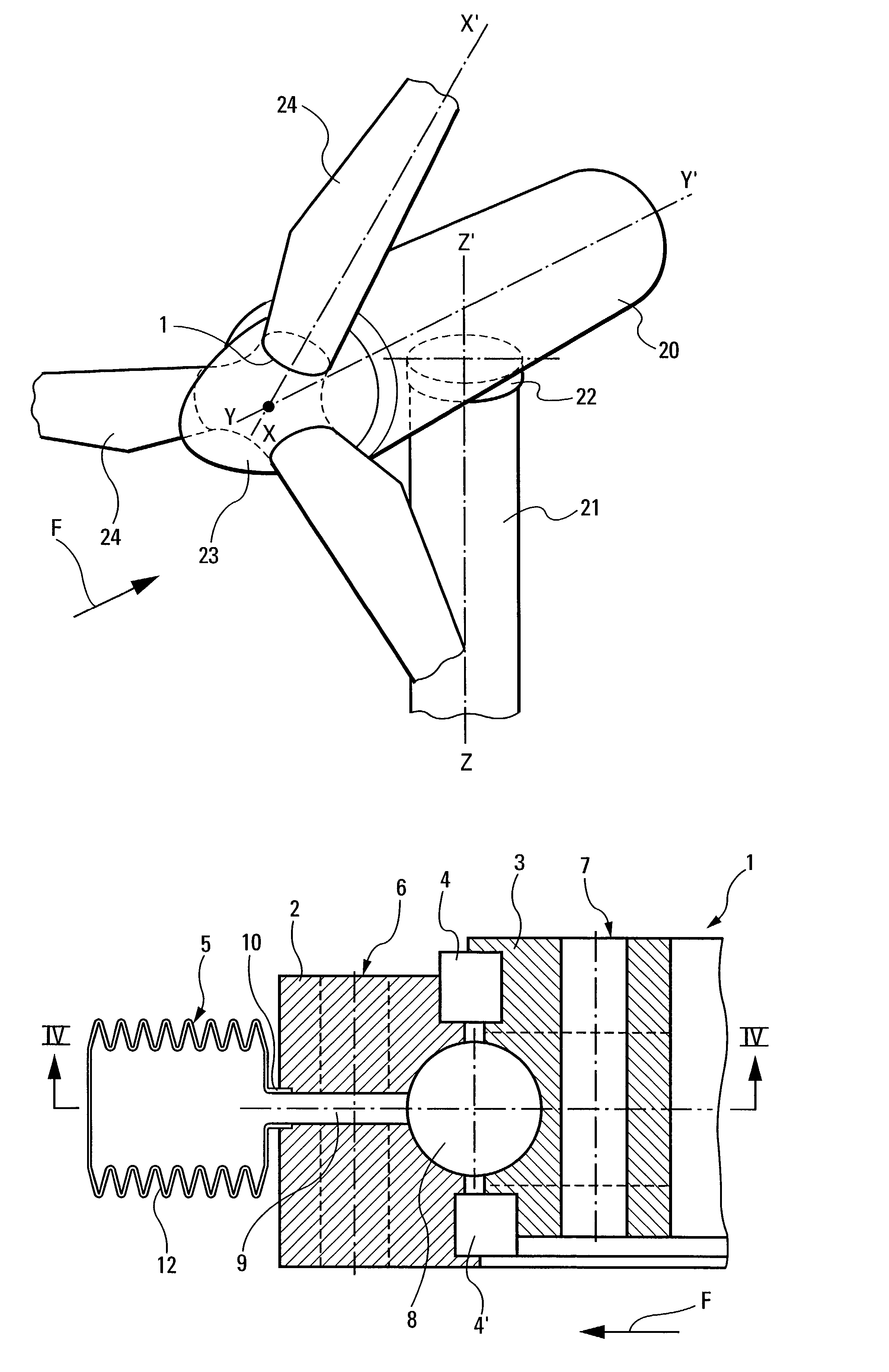
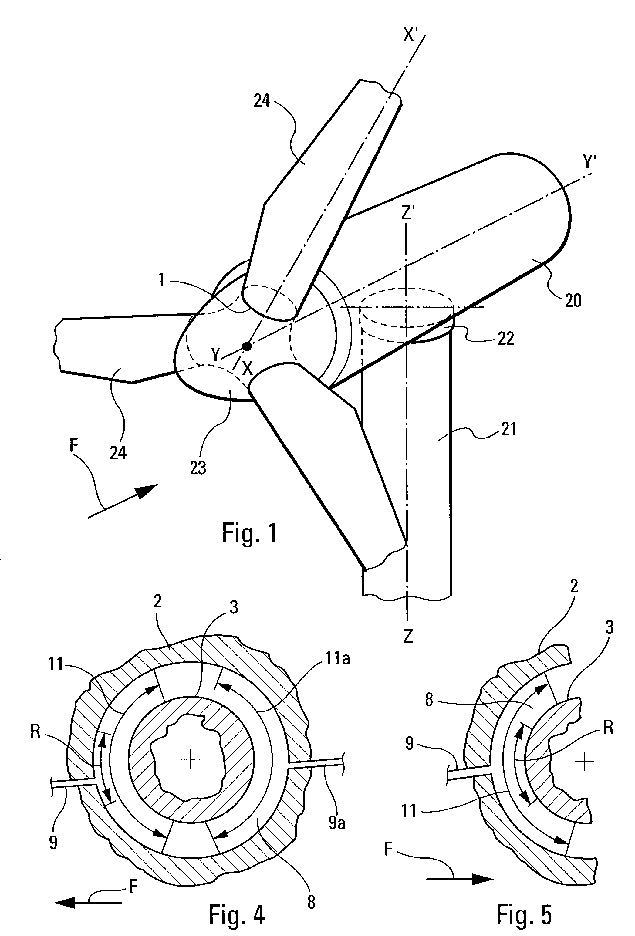
[0028]In FIG. 1, the wind turbine comprises a pod 20 rotatably mounted on a vertical mast 21 through a first set of bearing races 22 so as to be rotatable about a vertical axis zz′ to be oriented according to the wind direction. The pod 20 is made integral with a stator within which is rotatably mounted a rotor 23 rotating about an axis yy′. Blades 24, for example three in number, are pivotally mounted on the rotor through a respective set of bearing races 1 so as to be rotatable about the blade's longitudinal axis xx′. Thus, the blade may be rotated about its axis in order to regulate the rotational velocity of the rotor as a function of wind velocity, and in particular, in order to maintain a substantially constant rotor rotational velocity irrespective of wind velocity.

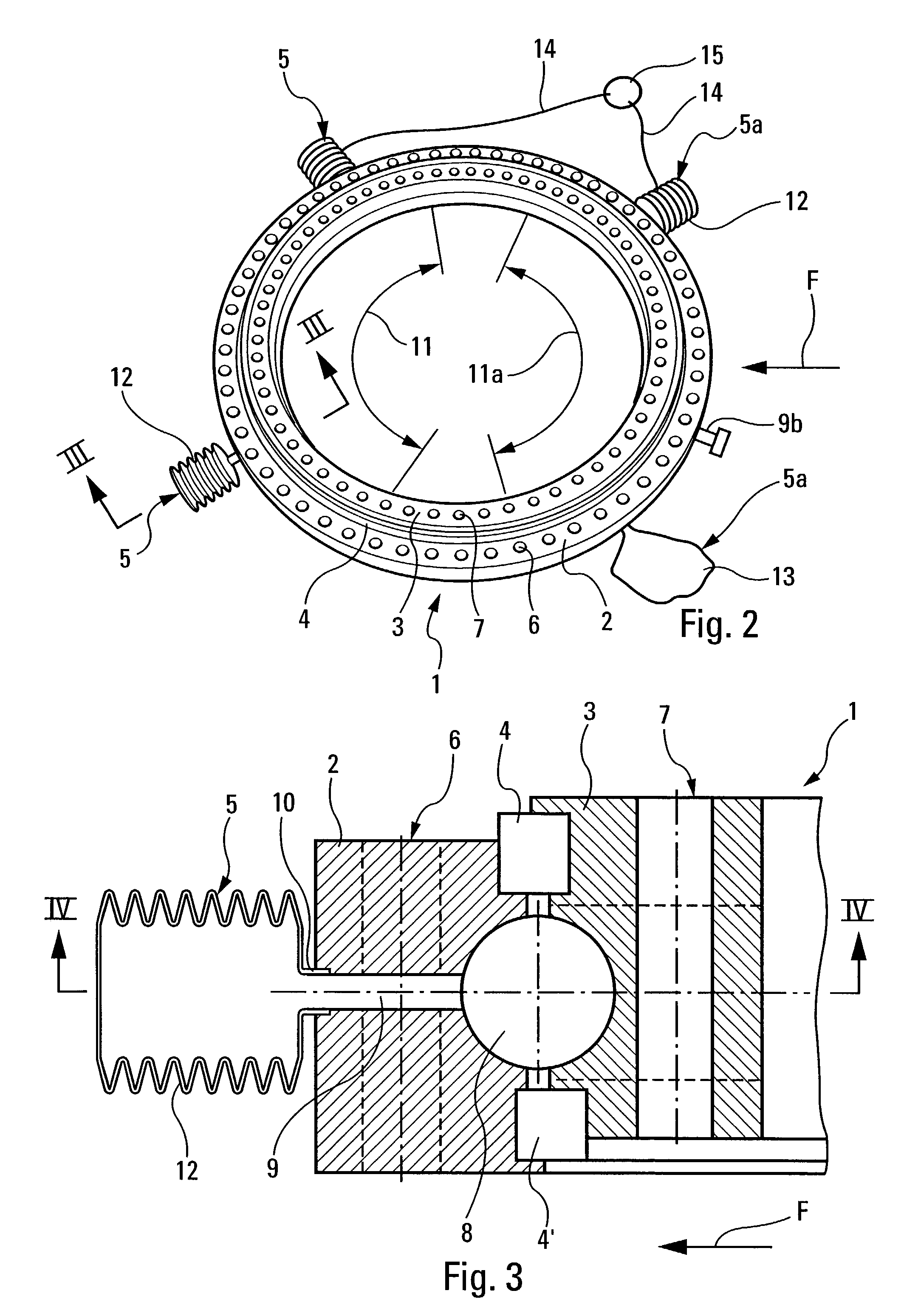
[0029]FIG. 2 is a detailed view of a set of orientation races 1 for a blade 24 of the wind turbine rotor 23. This set comprises two concentric races 2, 3, namely an outer race 2 attached to the wind turbine rotor ...


PUM


Abstract

For a bearing mounted between two concentric races rotating relative to each other, and forming an annular gap that accommodates the bearing and is closed by seals, at least one grease tube is provided between the periphery of one of the two races and the annular gap, and is connected to a corresponding grease reservoir. At least one main grease tube opens into the annular gap in an angular sector where an overpressure occurs, a corresponding main grease reservoir is adapted to collect grease flowing from the annular gap through the main grease tube due to the overpressure that may occur within the annular gap in the angular sector.

Description

BACKGROUND OF THE INVENTION[0001]The present invention relates to a device for improving the lubrication of ball or roll bearings.[0002]In particular, although not exclusively, it applies to the orientation races of orientable blades in wind turbines having a rotor, the rotational axis of which is permanently oriented substantially along the wind direction. More generally, it applies to any turbine with orientable blades, which is driven by a fluid with its rotational axis parallel to the fluid's flow direction, as well as any bearing used under comparable conditions.[0003]Such wind turbines are generally mounted on top a mast and comprise a stator attached so as to be rotatable about the mast axis and thus, to be oriented according to the wind direction, and a rotor supporting a number of blades. For the rotational velocity of the rotor to be controlled and, particularly, so that it does not exceed a certain limit, the blades are pivotally mounted on the rotor so as to be rotatable...

Claims


Application Information

Patent Timeline
Patent Type & Authority Patents(United States)
IPC IPC(8): F16C33/06F03D11/00F03D80/70F16C33/66F16N7/36
CPCF03D11/0008F16C33/6607F16C33/6622F16C2360/31F16N7/36Y02E10/722F16C2300/14F16C19/16F03D80/70Y02E10/72
Inventor JACQUEMONT, ERICERRARD, GERMAIN
Owner DEFONTAINE
Why Eureka
Try Eureka