Check patentability & draft patents in minutes with Patsnap Eureka AI!

Method for replacing used reaction cuvettes in an automatic analyzer depending upon next scheduled assay

an automatic analyzer and reaction cuvette technology, applied in chemical methods analysis, laboratory glassware, instruments, etc., can solve the problems of inability to fully restore a cleaned used cuvette, inaccurate assays of certain highly sensitive assays, and challenges in analytical clinical technology

Inactive Publication Date: 2006-01-31
SIEMENS HEALTHCARE DIAGNOSTICS INC
View PDF5 Cites 5 Cited by
  • Summary
  • Abstract
  • Description
  • Claims
  • Application Information

AI Technical Summary

Benefits of technology

This approach ensures accurate test results by automatically discarding and replacing cuvettes when an illegal A-B pair is detected, reducing the risk of assay inaccuracies and maintaining cost-effectiveness by minimizing the need for new cuvettes while ensuring analytical precision.

Problems solved by technology

Although various known clinical analyzers for chemical, immunochemical and biological testing of samples are available, analytical clinical technology is challenged by increasing needs for improved levels of analysis.
What has been overlooked, however, in many such cleaning systems, is that washing techniques are not fully capable of restoring a cleaned used cuvette to the degree of cleanliness of an unused cuvette.
Certain highly sensitive assays may be caused to have inaccurate results if certain reagent residues from preceding reaction assays are present in a re-washed reaction cuvette.
One solution is to simply use a new reaction cuvette for each new assay however this defeats the desire to achieve lower costs-per-reportable result.
From this discussion of the art state in automated clinical analyzers, it may be seen that while has been considerable progress has been made toward increasing assay processing efficiency, there remains an unmet need for a method for determining whether or not washing and reusing a reaction cuvette in an analyzer can be done without sacrificing assay quality.
In particular, there remains an unmet need for determining not to reuse a cleaned reaction cuvette when the assay scheduled to be next performed in said cleaned reaction cuvette may be adversely affected by reagents employed in the assay previously performed in said cleaned reaction cuvette.

Method used


Image

  • Method for replacing used reaction cuvettes in an automatic analyzer depending upon next scheduled assay
  • Method for replacing used reaction cuvettes in an automatic analyzer depending upon next scheduled assay
  • Method for replacing used reaction cuvettes in an automatic analyzer depending upon next scheduled assay

Examples


Embodiment Construction

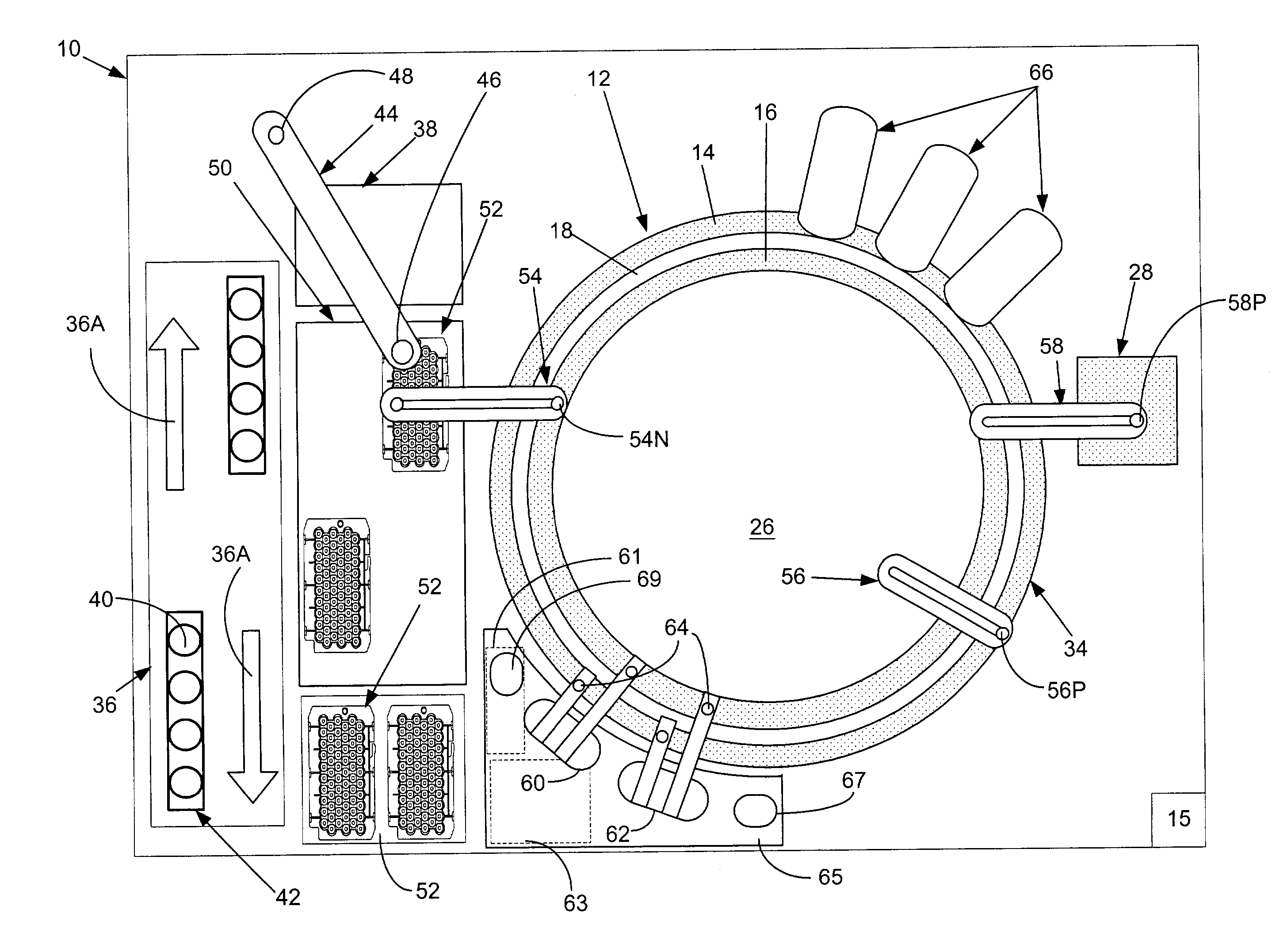
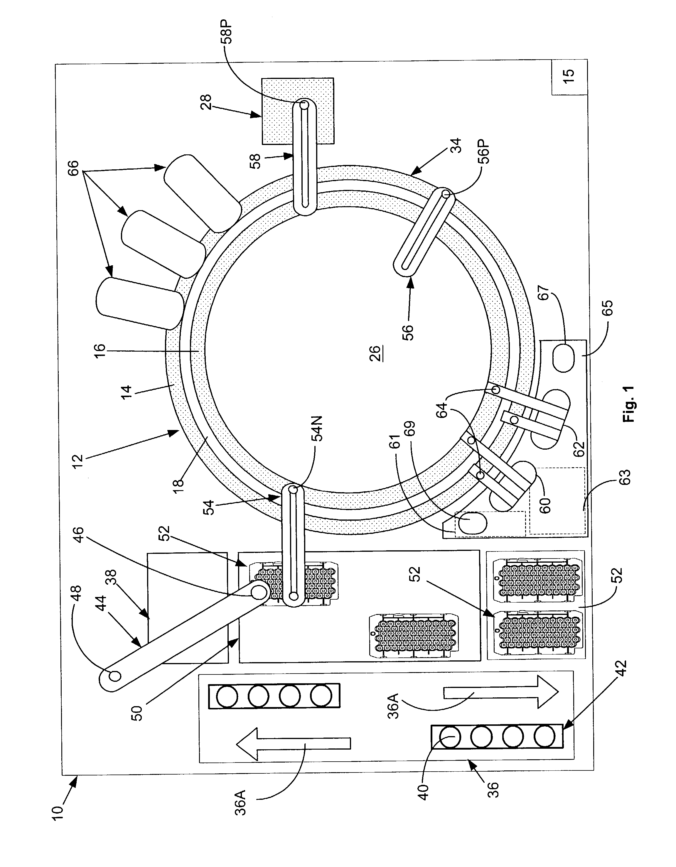
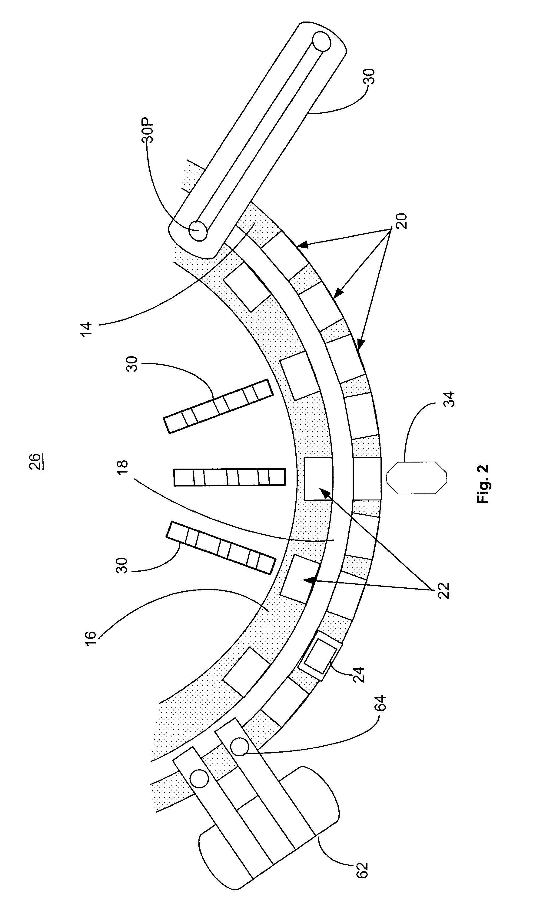
[0016]FIG. 1, taken with FIG. 2, shows schematically the elements of a single conventional automatic chemical analyzer 10 convenient for practicing the present invention and comprising a reaction carousel 12 supporting an outer cuvette carousel 14 of cuvette ports 20 and an inner cuvette carousel 16 of cuvette ports 22, the outer cuvette carousel 14 and inner cuvette carousel 16 being separated by a open groove 18. Cuvette ports 20 and 22 are adapted to receive a plurality of reaction cuvettes 24 typically formed as small, flat walled, U-shaped containers (see FIG. 5) with an open central reaction portion closed at the bottom and with an opening at the top of the cuvettes 24 to allow the addition of reagent and sample liquids. Reaction carousel 12 is rotatable using stepwise movements in a constant direction at a constant velocity, the stepwise movements being separated by a constant dwell time during which dwell time, carousel 12 is maintained stationary and an assay device located...


PUM

PropertyMeasurementUnit
concentrationaaaaaaaaaa
chemicalaaaaaaaaaa
pressuresaaaaaaaaaa

Abstract

A method for determining not to reuse a previously used and cleaned reaction cuvette in an analyzer when an assay scheduled to be performed may be adversely affected by contaminants remaining in the cleaned reaction cuvette. If determined not to reuse a previously used and cleaned reaction cuvette, the previously used and cleaned reaction cuvette is replaced with an unused new reaction cuvette.

Description

FIELD OF THE INVENTION[0001]The present invention relates to a method and apparatus for automatically processing a patient's biological fluids such as urine, blood serum, plasma, cerebrospinal fluid and the like. In particular, the present invention provides a method to determine whether or not to reuse a reaction cuvette in a analyzing system by considering the identity of an assay scheduled to be next performed therein.BACKGROUND OF THE INVENTION[0002]Various types of tests related to patient diagnosis and therapy can be performed by analysis assays of a sample of a patient's infections, bodily fluids or abscesses. Such patient samples are typically placed in sample vials, extracted from the vials, combined with various reagents in special reaction cuvettes or tubes, incubated, and analyzed to aid in treatment of the patient. In typical clinical chemical analyses, one or two assay reagents are added at separate times to a liquid sample having a known concentration, the sample-reag...

Claims


Application Information

Patent Timeline
Patent Type & Authority Patents(United States)
IPC IPC(8): G01N21/00G01N35/00G01N35/02
CPCG01N35/02G01N2035/00277Y10T436/115831Y10T436/11Y10T436/12
Inventor DEVLIN, SR, WILLIAM JACKSONFRYE, STEVEN LAWRENCEMILLER, DAVID JEFFREYPANKRATZ, THOMAS JOHN
Owner SIEMENS HEALTHCARE DIAGNOSTICS INC
Features
  • R&D
  • Intellectual Property
  • Life Sciences
  • Materials
  • Tech Scout
  • Unparalleled Data Quality
  • Higher Quality Content
  • 60% Fewer Hallucinations
Learn More